SMARC T335x Carrier Board Hardware Design Guide, Document Revision 1.2
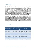
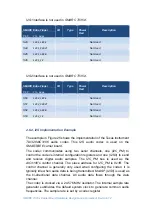
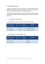
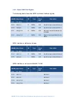
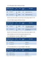
SER3 (Debug Port)
interface is defined as follows.
SMARC Edge Finger
I/O
Type
Power
Rail
Description
Pin#
Pin
Name
P140
SER3_TX
O
CMOS
3.3V
Asynchronous serial port data out
P141
SER3_RX
I
CMOS
3.3V
Asynchronous serial port data in
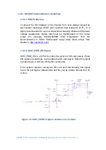
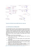
2.8.2. Asynchronous Interface Implementation Guidelines
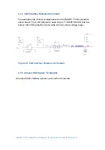
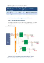
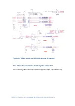
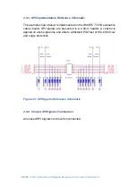
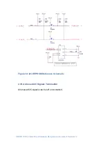
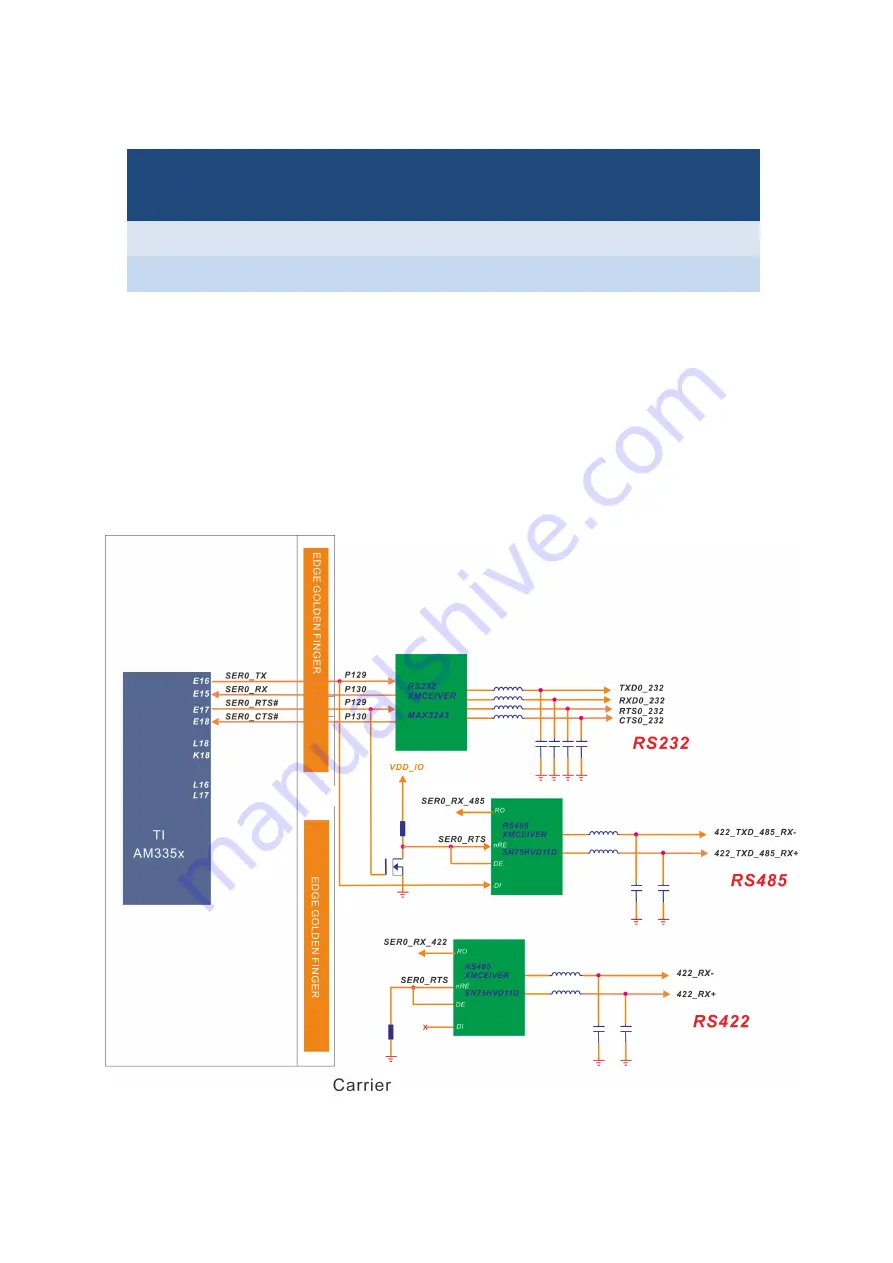
2.8.2.1. RS232/422/485 System Diagram
The diagram below shows the system diagram of RS232, 422 and 485. An
external transceiver is used to convert the logic-level signals to desired
physical interface.
Figure 29: RS232, RS422 and RS485 System Block Diagram


