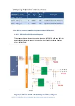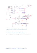
SMARC T335x Carrier Board Hardware Design Guide, Document Revision 1.2
2.6 I2S Audio Interface
The
SMARC
specification defines minimum configuration of one (1) I2S
interface up to a maximum of three (3) ports and one of them (
I2S2
) may
alternatively be used to implement a
HDA
(High Definition Audio) channel.
I2S
interfaces are typically used for connection to
I2S
audio
CODEC
. This
interface is also useful for connection to peripherals such as baseband
modems, touch controllers, etc. A common audio master clock signal is also
defined.
SMART T335X
features one
I2S
interface (
I2S0
) that delivers stereo
audio line output and processes stereo audio line input.
I2S0
interface of
SMARC T335X
is implemented from
McASP
interfaces of
Sitara
AM335x
.
The
SMART-BEE
incorporates a Texas Instruments
TLV320AIC3106
stereo
codec for input and output of audio signals. The codec samples analog signals
on the microphone or line inputs and converts them into digital data so it can
be processed by the AM335x processor. When the processor is finished with
the data it uses the codec to convert the samples back into analog signals on
the line output so the user can hear the output.
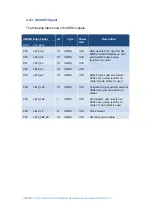
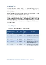
2.6.1. I2S Signal
s
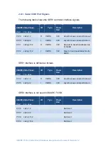
The following table shows the
I2S0
signals.
SMARC Edge Finger
I/O
Type
Power
Rail
Description
Pin#
Pin
Name
S38
AUDIO_MCK
O
CMOS
3.3V
Master clock output to Audio
codecs, not used, uses an
external 24.576Mhz oscillator
S39
I2S0_LRCK
IO
CMOS
3.3V
Left& Right audio synchronization
clock
S40
I2S0_SDOUT
O
CMOS
3.3V
Digital audio Output
S41
I2S0_SDIN
I
CMOS
3.3V
Digital audio Input
S42
I2S0_CK
O
CMOS
3.3V
Digital audio clock

