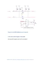
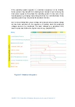
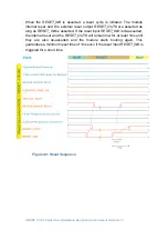
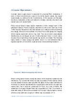

SMARC T335x Carrier Board Hardware Design Guide, Document Revision 1.2
Chapter 3 Power Design Guideline
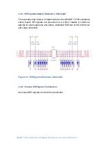
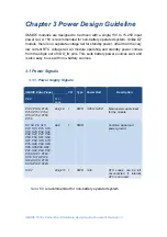
SMARC
modules are designed to be driven with a 3V to +5.25V input
power rail. A +5V is recommended for non-battery operated system. Unlike Q7
module, there is no separate voltage rail for standby power, other than the very
low current RTC voltage rail. All module operating and standby power comes
from the single set of
VDD_IN
pins. This suits battery power sources well, and
is also easy to use with non-battery sources.
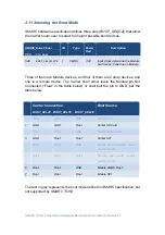
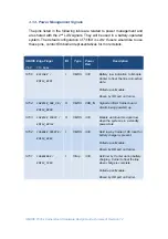
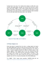
3.1 Power Signals
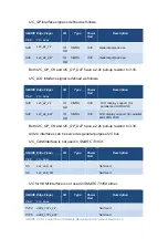
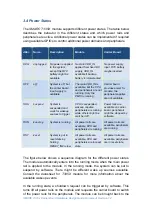
3.1.1. Power Supply Signals
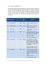
SMARC Edge Finger
I/O
Type
Power Rail
Description
Pin#
Pin
Name
P147, P148, P149,
P150, P151,P152,
P153, P154, P155,
P156
VDD_IN
I
PWR
3.35V~5.25V
1
Main power supply input
for the module
P2, S3, P9, S10,
P12, S13, P15, S16,
P18, S25, P32, S34,
P38, S47, P47, P50,
P53, P59, S61, S64,
S67, P68, S70, S73,
P79, S80, P82, S83,
P85, S86,P88, S89,
P91, S92, P94, P97,
P100, S101, P103,
S110, S119, P120,
S124, S130, P133,
S136, P142, S143
GND
I
PWR
Common signal and
power ground
S147
VDD_RTC
I
PWR
3.3V
RTC supply, can be left
unconnected if internal
RTC is not used
Note:
5V is recommended for non-battery operated system.


