
SMARC T335x Carrier Board Hardware Design Guide, Document Revision 1.2
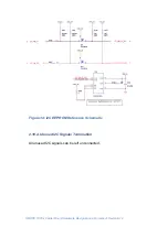
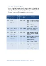
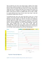
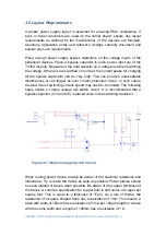
When main power is supplied from the carrier, a voltage detector will assert
VIN_PWR_BAD#
signal to tell the module and carrier that the power is good.
VDD_IO_SEL#
will be pulled high on carrier that represents a 3.3V
VDD_IO
carrier. These two signals will turn on the PMIC on module to power on the
module. Because
T335X
supports only 3.3V I/O, the module will pull the
VDD_IO_SEL#
pin to the module
VDD_IN
rail through a resistance of 100K.
The module will not power up if the module senses a low level on the
VDD_IO_SEL
# (due to the carrier pulling the line down) and the Module
supports only 3.3V I/O or receives a low-active
VIN_PWR_BAD#
signal.
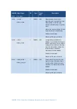
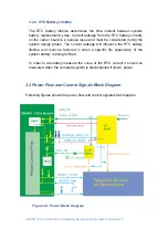
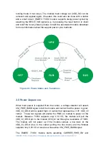
Carrier power circuits in the carrier Power domain should not power up unless
the module asserts
CARRIER_PWR_ON
. The module signal
CARRIER_PWR_ON
exists to ensure that the module is powered before the
main body of carrier circuits (those outside the power and power control path
on the carrier).
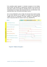
The main body of carrier board circuits will not be powered until the module
asserts the
CARRIER_PWR_ON
and
VDD_IO_SEL#
signals as a high.
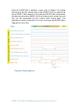
Module hardware will assert
CARRIER_PWR_ON and VDD_IO_SEL#
when
all module supplies necessary for module booting are up. The module will
continue to assert signal
RESET_OUT
# after the release of
CARRIER_PWR_ON
, for a period sufficient to allow carrier power circuits to
come up.
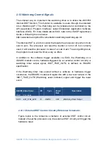
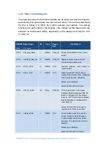
If users would like to have SD boot up,
SDIO_PWR_EN
signal have to be pull
up to 3.3V on carrier.
Module and carrier power supplies will not be enabled if the
VIN_PWR_BAD#
is held low by carrier. It is a power bad indication signal from carrier and is
100k pull up to
VDD_IN
on module.


