SMARC T335x Carrier Board Hardware Design Guide, Document Revision 1.2
2.3.2.4 Routing Considerations for USB
See
SMARC T335X
layout guide for trace routing guidelines and the
SMARC
specification for more information about this subject.
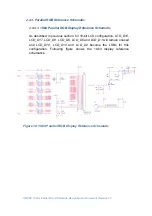
2.3.3. USB Reference Schematic
2.3.3.1. USB Host Reference Schematic
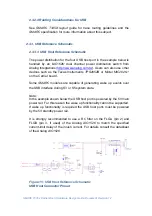
The power distribution for the four USB host port in the example below is
handled by an 'AIC1526' dual channel power distribution switch from
Analog Integrations (
http://www.analog.com.tw
). Users can also use other
devices such as the Texas Instruments
TPS2052B
or Micrel
MIC2026-1
on the Carrier board.
Some
SMARC
modules are capable of generating wake up events over
the USB interface during S3 or S5 system state.
Note:
In the example shown below the USB host port is powered by the 5V main
power rail. For this reason the wake up functionality cannot be supported.
If wake up functionality is required the USB host ports must be powered
by the 5V standby power rail.
It is strongly recommended to use a RC filter on the FLGA (pin 2) and
FLGB (pin 3, if used) of the Analog
AIC1526
to match the specified
current-limit delay of the inrush current. For details consult the datasheet
of the Analog
AIC1526
.
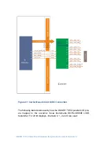
Figure 15: USB Host Reference Schematic
USB Host Connector Pinout

