SMARC T335x Carrier Board Hardware Design Guide, Document Revision 1.2
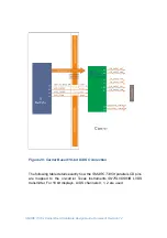
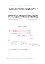
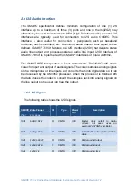
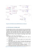
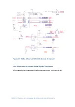
Figure 25: AIC3106 I2S Audio CODEC Reference Schematic
2.6.3. I2S Placement and Routing Guide
The implementation of proper component placement and routing techniques
will help to ensure that the maximum performance available from the codec
is achieved. Routing techniques that should be observed include properly
isolating the codec, associated audio circuitry, analog power supplies, and
analog ground planes from the rest of the carrier board. This includes split
planes and the proper routing of signals not associated with the audio
section.
The following is a list of basic recommendations:
Traces must be routed with a target impedance of 55
Ω
with an
allowed tolerance of
±
15%.
Ground return paths for the analog signals must be given special
consideration.
Digital signals routed in the vicinity of the analog audio signals must
not cross the power plane split lines. Locate the analog and digital
signals as far as possible from each other.
Partition the carrier board with all analog components grouped
together in one area and all digital components in another.
Keep digital signal traces, especially the clock, as far as possible from

