SMARC T335x Carrier Board Hardware Design Guide, Document Revision 1.2
4.4 Module “Z” Height Consideration
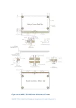
Note from Figure 46 Module Mechanical Outline
above that the component
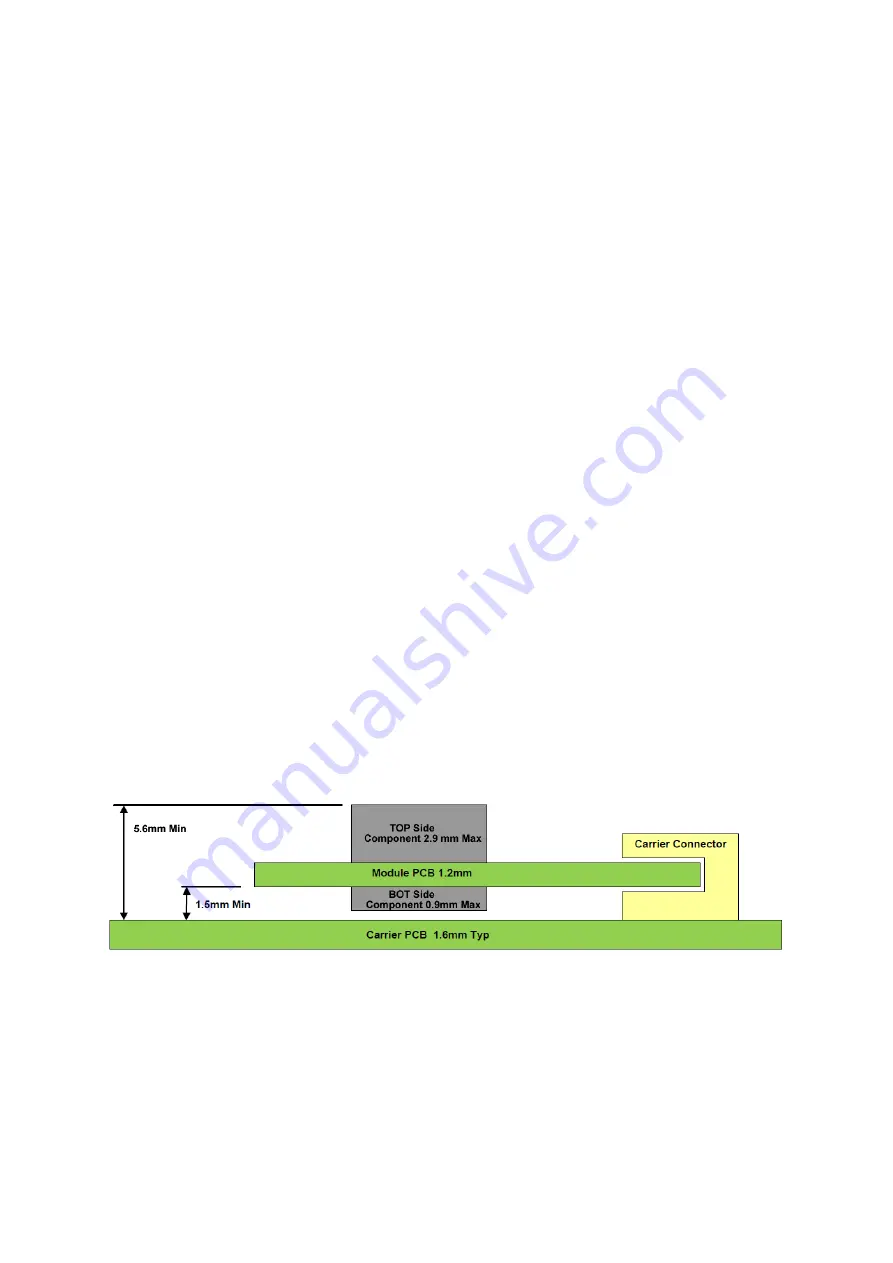
height on the Module is restricted to a maximum component height of 2.9mm
on the Module Primary (Top) side and to 0.9mm on the Module Secondary
(Bottom) side.
The 0.9mm Secondary side component height restriction allows the Module to
be used with 1.5mm stack-height Carrier connectors. When used with 1.5mm
stack height connectors, the ‘Z’ height profile from Carrier board Top side to
tallest Module component is 5.6mm.
When a 1.5mm stack height Carrier board connector is used, there shall not be
components on the Carrier board Top side in the Module region. Additionally,
when 1.5mm stack height connectors are used, there should not
be PCB
traces on the Carrier top side in the Module shadow. This is to prevent possible
problems with metallic Module heat sink attachment hardware that may
protrude through the Module.
If Carrier board components are required in this region, then the Carrier
components must be on the Carrier Bottom side, or a taller board-to-board
connector may be used. Stack heights of 2.7mm, 3mm, 5mm and up are
available. The one used on
SMART-BEE
evaluation carrier is 5mm.
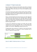
The figure below shows the minimum “Z” height from Carrier board Top side to
tallest Module component. The dimensions of those components must of
course be considered in a system design.
Figure 47: SMARC T335X Module Minimum “Z” Height

