SMARC T335x Carrier Board Hardware Design Guide, Document Revision 1.2
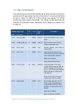
3.1.3. Power Management Signals
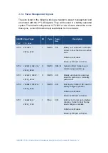
The pins listed in the following table are related to power management and
are shared with the 2
nd
LAN
signals. They will be used in a battery-operated
system. The default configuration of
T335X
is
LAN
. If users would like to use
these pins, contact Embedian representatives for more details.
SMARC Edge Finger
I/O
Type
Power
Rail
Description
Pin#
Pin
Name
S156
BATLOW#
/
RMII2_RXD1
I
CMOS
3.3V
Battery low indication to Module.
Carrier to float the line in in-active
state.
Pulled up on Module.
Driven by OD part on Carrier.
S154
CARRIER_PWR_ON
/
RMII2_RXD0
O
CMOS
VDD_IN
Signal to inform Carrier board
circuits being powered up
S153
CARRIER_STBY#
/
RMII2_RXCLK
O
CMOS
3.3V
Module will drive this signal low
when the system is in a standby
power state
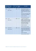
S152
CHARGER_PRSNT#
/
RMII2_RXER
I
CMOS
3.3V
Held low by Carrier if DC input for
battery charger is present.
Pulled up on Module.
Driven by OD part on Carrier.
S151
CHARGING#
/
RMII2_TXEN
I
Strap
3.3V
Held low by Carrier during battery
charging. Carrier to float the line
when charge is complete.
Pulled up on Module.
Driven by OD part on Carrier.

