SMARC T335x Carrier Board Hardware Design Guide, Document Revision 1.2
2.3.2. USB Implementation Guidelines
2.3.2.1. USB Over-Current Protection and Power Enable Signal
(USB_EN_OC#)
The USB Specification describes power distribution over the USB port,
which supplies power for USB devices that are directly connected to the
carrier board. Therefore, the host must implement over-current protection
on the ports for safety reasons. Should the aggregate current drawn by
the downstream ports exceed a permitted value, the over-current
protection circuit removes power from all affected downstream ports. The
over-current limiting mechanism must be resettable without user
mechanical intervention. For more detailed information about this subject
refer to the 'Universal Serial Bus Specifications Revision 2.0', which can
be found at
http://www.usb.org
.
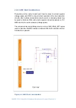
Over-current protection for USB ports can be implemented by using power
distribution switches on the carrier board that monitors the USB port
power lines. Power distribution switches usually have a soft-start circuitry
that minimizes inrush current in applications where highly capacitive loads
are employed. Transient faults are internally filtered. Additionally, they
offer a fault status output that is asserted during over-current and thermal
shutdown conditions. These outputs should be connected to the
corresponding
SMARC
module's USB over-current sense signals.
Carrier Board USB peripherals that are not removable often do not make
use of USB power switches with current limiting and over-current
detection. It is usually deemed un-necessary for non-removable devices.
In these cases, the
USBx_EN_OC#
pins may be left unused, or they may
be used as
USBx
power enables, without making use of the over-current
detect Module input feature.
Usually, the Module
USBx_EN_OC#
pins (where ‘x’ is 0 or 1 for use with
USB0
or
USB1
) are multi-function Module pins, with a 10k pull-up to a
3.3V rail on the Module, an OD driver on the Module, and, if the
OC#
(over-current) monitoring function is implemented on the Carrier, an OD
driver on the Carrier. However, TI Sitara AM335X does not require pull up
on
USBx_EN_OC#
pins. The use is as follows:
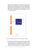
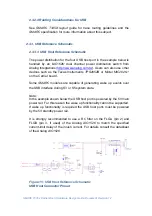
1) On the Carrier board, for external plug-in USB peripherals (USB
memory sticks, cameras, keyboards, mice, etc.) USB power
distribution is typically handled by USB power switches such as the
Texas Instruments
TPS2052B
or the Micrel
MIC2026-1
or similar
devices. The Carrier implementation is more straightforward if the

