V&T Technologies Co., Ltd.
http://www.ecodrivecn.com
Appendix A Modbus Communication Protocol
134
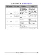
PDU Part Contents
Data Length (Byte)
Range
Function code
1
0x17
Read the number of
bytes in the register
1
0x02~0x20
Read data contents
2*Read bytes
0x0000~0xFFFF
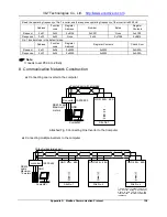
Operating sequence: Read firstly and rewrite secondly, but the register 0xF080 is an exception, which
shall be written firstly and read secondly so as to facilitate the management of the operation panel.
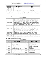
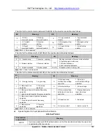
5. Inverter Register Address Distribution
Attached Table-1
Address Space
Meaning
0x0000 ~ 0x1A00
The corresponding relationship between the function codes of the inverter and the
Modbus protocol register address. The bytes at higher orders refer to function code
groupnumber. The bytes at lower orders refer to groupnumber, express with HEX
adecimal. P0 to PE, d0, d1, d2, H0
、
H1
、
H2
、
A0
、
C0
、
U0
、
U1 corresponds to the bytes
at higher orders such as 0x00 to 0x0E, 0x0F, 0x10, 0x11,0x12
、
0x13
、
0x14
、
0x15
、
0x16
、
0x17
、
0x18. for example,the Modbus address of function code Pb.23 is
(0x0b<<8)+23=0x0b17
0x4000 ~ 0x5A00
The corresponding relationship between the function code attribute word of the inverter
and the Modbus protocol register address. The bytes at higher orders refer to the
function code group No. plus 0x40, while the bytes at lower orders refer to serial No. in
the group, for example, 0x4b17 corresponds to the attribute word of the function code
Pb.23. The attribute words are defined in the following order: Bit0 ~ Bit2 for unit, Bit3 ~
Bit4 for modifying attribute, Bit5 ~ Bit6 for precision and Bit7 ~ Bit15 for reserved
purpose.
0x8000 ~ 0x800D
The register for control word of the inverter. Refer to Attached Table 2 for details.
0x810B ~ 0x8193
The register for status word of the inverter. Refer to Attached Table 3 for details.
0xF000 ~ 0xF002
Special register for input password authentication. Refer to Attached Table 4 for details.
0xF080~ 0xF084
Read the current value, upper limit, lower limit, and factory default value of the function
code, and rewrite the function code. Refer to Attached Table 5for details.
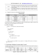
Register for control word of the inverter.
Attached Table-2
Register
address
Name of Parameters
Register
address
Name of Parameters
0x8000
Control command word
0x8007
AO2 output host computer
percentage
0x8001
Open loop digital frequency
reference
0x8008
Y2 output host computer
percentage
0x8002
Running command reference mode
0x8009
Slave setting frequency scale
coefficient
0x8003
Open loop main reference mode
0x800A
Virtual terminal
0x8004
Close loop digital voltage reference
0x800B
Y1 terminal output function
0x8005
Close loop digital rotation velocity
reference
0x800C
Acceleration time 0
0x8006
AO1 output host computer
percentage
0x800D
Deceleration time 0

