V&T Technologies Co., Ltd.
http://www.ecodrivecn.com
Chapter 3 Wiring of Inverter
26
Type
Terminal
symbol
Terminal function
description
Technical specification
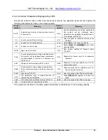
Relay output
RA/RB/RC
Relay output
RA-RB: Normally closed
RA-RC: Normally open
Contact capacity: 250VAC/1A, 30VDC/1A
Note:
﹡
If the user connects adjustable potentiometer between
+
10V and GND, the resistance of the
potentiometer shall be no less than 5
kΩ,
Note:
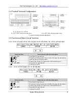
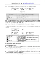
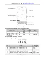
1. The arrangement sequence of the control circuit terminals is as follows:
+10V
AI1
AI2
AI3
GND
AO1
AO2
GND
485+
485-
RA
RB
RC
+24V
PLC
COM
X1
X2
X3
X4
X5
X8
X7/DI
Y1
Y2/DO
COM
+10V
AI1
AI2
AI3
GND
AO1
AO2
GND
485+
485-
RA
RB
RC
+24V
PLC
COM
X1
X2
X3
X4
X5
X8
X7/DI
Y1
Y2/DO
COM
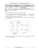
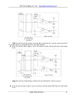
2. Wiring mode of the multi-functional input/output terminals
When the in24V power supply of the inverter is used, the external controller adopts NPN sink
current wiring mode.
When the in24V power supply of the inverter is used, the external controller adopts PNP
draw-off current wiring mode.
User
controller
Inside of inverter
The near end of the
shielding
cable is grounded
+24
User
Controller
Inside of inverter
The near end of
the shielding cable
is grounded
+24V


