V&T Technologies Co., Ltd.
http://www.ecodrivecn.com
Chapter 6 Parameter Description
84
69~98: Reserved.
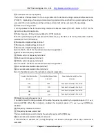
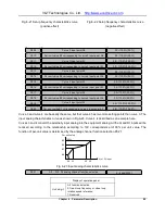
It can properly enlarge the setup value of P5.07 to improve the anti-interference capability of the terminal.
The longer the terminal filter time is, the longer the delay time of the terminal action is.
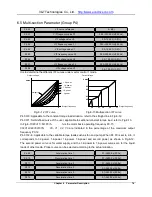
When the pulse input of the multifunctional input terminal X7/DI acts as open loop frequency reference or
analog feedback close loop reference (e.g. P0.04=4 or P1.02=4), the maximum input pulse frequency
determined via this functional code.
When the pulse input acts as open loop frequency reference, maximum input pulse frequency P5.10
corresponds to maximum output frequency P0.11, the current pulse input frequency f
P
and open loop
frequency reference f can be calculated as per the following formula: f=f
P
× P0.11/ P5.10.
When the pulse input acts as close loop frequency reference, maximum input pulse frequency P5.10
corresponds to maximum digital voltage reference 10V, the current pulse input frequency f
P
and analog
feedback close loop reference V
P
can be calculated as per the following formula: v
P
=f
P
× 10V/ P5.10.
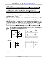
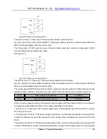
P5.11 is used to set the mode of controlling the startup and stop of the inverter with FWD and REV
terminals in the terminal running command reference mode.
0: Two line 1;
COM
FWD
REV
K1
K2
变
频
器
Inverter
COM
FWD
REV
K1
K2
变
频
器
Inverter
Fig.6-14 Two-line running mode 1
1: Two line 2;
COM
FWD
REV
K1
K2
变
频
器
Inverter
COM
FWD
REV
K1
K2
变
频
器
Inverter
Fig.6-15 Two-line running mode 2
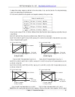
2: Three line 1;
FWD
REV
Start-up and
stop
command
0
0
Stop
0
1
Reverse
1
0
Forward
1
1
Stop
FWD
REV
Start-up
0
0
Stop
0
1
Stop
1
0
Forward
1
1
Reverse
P5.07
X1 to X7 terminal filtering time
0.000~1.000 s (0.001s)
P5.10
Maximum input pulse frequency
0.1~ 50.0 kHz (10.0 kHz)
P5.11
Startup/stop mode Selection
0 ~ 3(0)


