V&T Technologies Co., Ltd.
http://www.ecodrivecn.com
Chapter 3 Wiring of Inverter
28
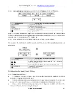
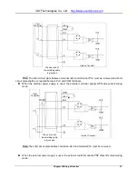
Note: The short circuit plate between te24V and terminal PLC must be removed.
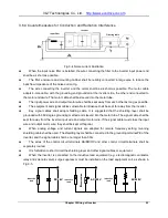
The wiring modes of the multi-functional output terminals when the in24V power supply of the
inverter and external power supply are used
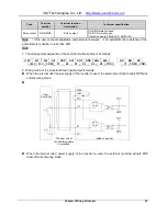
Note: When this wiring mode is adopted, if Y1 or Y2 terminal is damaged, the polarity of the external
diode must be checked to ensure the correctness.
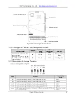
3.9 Schematic Diagram of Control Board
User
controller
Inside of inverter
The near end of the
+24
+24V
Inside of inverter
The near end of
the shielding cable
is grounded
User
Controller
Inside of inverter
Relay
+24
Inside of inverter
Relay
+24V
Inside of inverter
Relay
+24
Inside of inverter
Relay
+24V

