background image

V&T Technologies Co., Ltd.  

http://www.ecodrivecn.com


Chapter 6    Parameter Description 

75 


P3.06 sets the initial frequency at the beginning of DC braking current injection during the shutdown   

P3.07 sets the DC braking current value. This value is presented as the percentage of the rated current 

of the inverter. It ranges from 0.0 ~ 90.0% upon variable torque load. 

P3.08 sets the action time of the DC braking current. 


For some production equipment, reverse operation may cause equipment damage. This function can be 

used to prevent reverse operation. P3.09 is set to forbid reverse operation by default upon delivery. 


When the motor rotation direction is opposite to the required direction of the equipment, the wire 

connection of any two terminals at the output side the inverter can be interchanged so that the forward 

rotation direction of the equipment is consistent with the forward rotation direction defined by the inverter.   

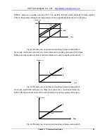
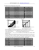
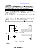
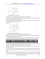
Set P3.10 to realize the waiting time for the zero-crossing of rotation speed when the inverter switches 

from forward rotation to reverse rotation (or from reverse rotation to forward rotation).   


Fig.6

11 Forward/reverse dead zone time 


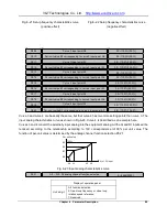
P3.11 is the frequency set for jog operation.   

Jog acceleration time P3.12: The time from zero to maximum frequency.   

Jog deceleration time P3.13: The time from maximum frequency to zero.   

When the inverter is in standby status, it can adopt jog operation. The jog operation command may come 

from the operation panel, multi-functional terminal or host computer.   

P3.08 

DC braking time


0.00~30.00 s (0.00s) 

P3.09 

Anti-reverse selection 

0~1(1) 

P3.10 

Forward/reverse dead zone time 

0.0~3600.0 s(0.0s) 

P3.11 

Jog frequency 

0.10~300.00 Hz (5.00Hz) 

P3.12 

Jog acceleration time 

0.1~60.0 s(6.0s) 

P3.13 

Jog deceleration time 

0.1~60.0 s(6.0s) 

输出频率

时间

P3.10

Output frequency 

Time 

输出频率

时间

P3.10

Output frequency 

Time 

Summary of Contents for V5-H Series

Page 1: ...product adopts speed sensorless vector control technology technology the internationally leading technology to offer excellent control performance and combines the application characteristics of Chin...

Page 2: ...ed Sensorless Vector Control Mode Realizing AC motor decoupling enabling the DC motorization of operation control Fig 1 indicates the four quadrant operation of the motor under speed sensorless vector...

Page 3: ...loading capability the inverter can realize stable tripless operation in any acceleration deceleration time and under any impact load condition With strong short time overload capability the inverter...

Page 4: ...ed identification and rotor magnetic flux orientation the torque responds quickly and stable operation in the case of 0 25Hz load mutation Startup torque Open loop vector control 0 25Hz 180 rated torq...

Page 5: ...ous power failure startup equipment such as chemical fiber and weaving equipment multi point synchronization linkage equipment fan pump etc Unique Speed Tracing Function It doesn t need special hardwa...

Page 6: ...the range of 0 to 300Hz the inverter can realize back electromotive force elimination and quick DC braking within 0 3s DC current input in the most efficient way to improve the braking capability The...

Page 7: ...tandard 18 5G to 75G as option to reduce the cost and the installation space Integrated built in expansion card design including injection molding machine interface card PG feedback card communication...

Page 8: ...up detection on the peripheral circuit such as motor grounding disconnection greatly improving the reliability of the system Comprehensive system protection function software hardware current limiting...

Page 9: ...y reference 50 4 Max main reference auxiliary reference 5 Min main reference auxiliary reference The sign of the main and auxiliary reference calculation positive or negative can automatically determi...

Page 10: ...ence operation panel reference 5 FASt bASE menu switch 6 Menu mode switching bASE FASt ndFt LASt bASE Host Computer Communication The operation panel and terminals provide 485 ports the communication...

Page 11: ...al secrets such as system specific process parameters cannot be copied User Self defined Parameter Display Function The user can choose the common parameters displayed by the operation panel and use t...

Page 12: ...e bobbiner and other equipment of the textile industry It supports the overload protection with motor temperature feedback Customized timed shutdown with the duration up to 100 hours The user can sele...

Page 13: ...edium wire drawing machine It features large torque upon low frequency operation and high speed stabilization precision Double conversion scheme It can realize the inverter application of the same pow...

Page 14: ...r torque output is stable to ensure the quality of the workpiece Tripless With extremely powerful loading capability the inverter can realize stable tripless operation in any acceleration deceleration...

Page 15: ...ccident or loss safety measures such as redundancy or bypass shall be taken Goods Arrival Inspection Note Note If the inverter is found to be damaged or lack parts the inverter cannot be installed Oth...

Page 16: ...inals U T1 V T2 and W T3 otherwise the inverter will be damaged It is forbidden to connect the output terminal of the inverter to the capacitor or LC RC noise filter with phase lead otherwise the inte...

Page 17: ...e heatsink and the braking resistor have high temperature Please do not touch such device otherwise you may be burnt When it is used on lifting equipment mechanical contracting brake shall also be equ...

Page 18: ...Note The circuit boards have large scale CMOS IC Please do not touch the board to avoid the circuit board damage caused by electro static Others Danger Danger It is forbidden to modify the inverter un...

Page 19: ...and Peripheral Devices 16 3 2 Description of Peripheral Devices for Main Circuit 17 3 3 Lectotype of mMain Circuit Peripheral Devices 17 3 4 Product Terminal Configuration 19 3 5 Functions of Main Cir...

Page 20: ...11 Control Parameter Group PA 102 6 12 Enhanced Function Parameter Group Pb 108 6 13 Communication Parameters Group PC 112 6 14 Vector Control 2 Parameters Group Pd 113 6 15 Failure Record Parameters...

Page 21: ...ions V5 H 4 T 11G 15L AX XX Vector control technology platform 2 200V 4 400V S Single prase T Three prase 00 99 Hardware nonstandard version A0 Z9 Software nonstandard version 11G 11kW Constant torque...

Page 22: ...0 3 60 69 3 86 104 124 150 201 Braking unit Built in as standard Built in as option Protection class IP20 Cooling mode Self cooling Forced air convection cooling Power kW 90 110 132 160 185 200 220 25...

Page 23: ...phase 0 to rated input voltage Rated current A 210 253 304 350 380 426 470 520 600 650 690 775 860 950 Overload capability 115 1 minute 160 0 5 second interval 10 minutes inverse time lag feature Inpu...

Page 24: ...e 325 375V Operating time 100 0s The braking unit can be selected for V5 H 4T18 5G 22L V5 H 4T75G 90L DC braking capability DC braking initial frequency 0 00 300 00Hz DC braking current Constant torqu...

Page 25: ...ipheral protection abnormal current detection output to ground short circuit abnormal power failure during operation abnormal input power output phase failure abnormal EEPROM abnormal relay contact te...

Page 26: ...duct component name 1 6 Product Outline Mounting Dimension and Weight Fig 1 2 Product outline and mounting dimension V5 H 2T0 4G V5 H 2T2 2G V5 H 4T7 5G 11L and below power class V5 H 4T11G 15L and ab...

Page 27: ...V5 H 4T5 5G 7 5L 155 249 185 136 232 69 8 5 5 4 5 V5 H 4T7 5G 11L V5 H 4T11G 15L 210 337 200 150 324 88 2 7 8 5 V5 H 4T15G 18 5L V5 H 4T18 5G 22L 289 440 220 200 425 88 2 5 7 17 V5 H 4T22G 30L V5 H 4...

Page 28: ...on to V5 H Series Inverter 8 Voltage class Inverter model Outline and mounting dimension mm Approximate weight kg W H D W1 H1 D1 T1 Mounting hole diameter 400V V5 H 4T400G V5 H 4T450L 810 1358 425 520...

Page 29: ...mension Note V5 H 4T7 5G 11L and below power class are equipped with shuttle type operation panel V6 DP01 as standard V5 H 4T11G 15L and above power class are equipped with button type operation panel...

Page 30: ...T3 7G 5 5L 550W 150 66 7 1 135 V5 H 4T5 5G 7 5L 800W 100 66 7 1 135 V5 H 4T7 5G 11L 1070W 75 66 7 1 130 V5 H 4T11G 15L 1600W 50 25 1 135 V5 H 4T15G 18 5L 2000W 40 25 1 125 V5 H 4T18 5G 22L B ui l t i...

Page 31: ...during the installation Mount the product vertically in the electric control cabinet mount the cooling fan or air conditioner to prevent the ambient temperature from rising to above 45 C For the site...

Page 32: ...al of operation panel As shown in Fig 2 3 the grab on the operation panel forcefully in direction 1 and then lift the panel body in direction 2 Mounting of operation panel As shown in Fig 2 4 align wi...

Page 33: ...ess the left and right sides of the cover forcefully in direction 1 and at the same time lift the cover in direction 2 as shown in Fig 2 5 Removal of upper cover As shown in Fig 2 6 press the left and...

Page 34: ...ng of lower cover Mounting of operation panel Please refer to 2 3 1 Removal and mounting of operation panel 2 3 3 Removal and Mounting of Covers of V5 H 4T11G 15L V5 H 4T75G 90L and Above Power Class...

Page 35: ...Opening of the door Press the latch following direction 1 in Fig 2 11 and open the door following direction 2 Removal of operation panel The operation panel is connected to the control board through...

Page 36: ...nnection of the Product and Peripheral Devices Fig 3 1 Connection diagram of the product and peripheral devices Power supply Contactor Input AC reactor DC reactor Inverter Grounding Motor Grounding Ci...

Page 37: ...er factor of the inverter shall be higher than 90 When the above situations occur install the AC reactor at the input end of the inverter or DC reactor to the DC reactor terminal Input noise filter Th...

Page 38: ...T90G V5 H 4T110L 315 250 M10 17 6 22 5 70 M10 14 0 15 0 35 V5 H 4T110G V5 H 4T132L 350 330 M10 17 6 22 5 100 M10 14 0 15 0 50 V5 H 4T132G V5 H 4T160L 400 330 M12 31 4 39 2 150 M12 17 6 22 5 75 V5 H 4T...

Page 39: ...scription R L1 S L2 T L3 Three phase AC input terminal 1 2 B1 DC reactor connecting terminal short circuited with copper bus upon delivery 2 B1 B2 Connecting terminal of braking resistor 2 B1 DC power...

Page 40: ...T110L V5 H 4T560L adopt the top in bottom out wiring mode Terminal symbol Terminal name and function description R L1 S L2 T L3 Three phase AC input terminal 1 2 DC reactor connecting terminal if don...

Page 41: ...urrent of the output end will cause adverse impact on the inverter and the peripheral devices It is suggested that when the motor cable is longer than 100m output AC reactor be installed Refer to the...

Page 42: ...shielding layer shall be grounded with 360 degree grounding method and sleeved into the metal tube The signal cable shall be kept far away from the inverter input wire and output motor wire If the si...

Page 43: ...V T Technologies Co Ltd http www ecodrivecn com Chapter 3 Wiring of Inverter 23 Fig 3 5 Application of inductive load surge suppressor...

Page 44: ...V T Technologies Co Ltd http www ecodrivecn com Chapter 3 Wiring of Inverter 24 3 7 Terminal Wiring Fig 3 6 Terminal wiring diagram take V5 H 4T5 5G 7 5L as an example...

Page 45: ...e range 24V 20 X7 DI Multi functional input or pulse input Multi functional input same as X1 X6 Pulse input 0 1Hz 50kHz voltage range 24V 20 COM 24V grounding Internal isolated with GND Digital output...

Page 46: ...ows 10V AI1 AI2 AI3 GND AO1 AO2 GND 485 485 RA RB RC 24V PLC COM X1 X2 X3 X4 X5 X8 X7 DI Y1 Y2 DO COM 10V AI1 AI2 AI3 GND AO1 AO2 GND 485 485 RA RB RC 24V PLC COM X1 X2 X3 X4 X5 X8 X7 DI Y1 Y2 DO COM...

Page 47: ...e Note The short circuit plate between terminal 24V and terminal PLC must be removed When the external power supply is used the external controller adopts PNP draw off current wiring mode User control...

Page 48: ...external power supply are used Note When this wiring mode is adopted if Y1 or Y2 terminal is damaged the polarity of the external diode must be checked to ensure the correctness 3 9 Schematic Diagram...

Page 49: ...g AI1 I is the current input 0 20mA V is the voltage input 0 10V 0 10V AI2 I is the current input 0 20mA V is the voltage input 0 10V 0 20mA AO1 I is the current output 0 20mA V is the voltage output...

Page 50: ...lf definable indicator On Flash Current display parameter is self defined see description of P2 group Green Hz A V Time indicator On Current display parameter is time Green No unit indicator Off Curre...

Page 51: ...n stop run status increase the input frequency or close loop input Decrease Key 1 In first level menu decrease function code according to edit bit 2 In second level menu decrease the function code dat...

Page 52: ...n Press M Off Release M 4 Switch the reference method of running command Press M key to switch the reference method of giving running command Via operation panel Via terminal Via host computer Via ope...

Page 53: ...0 P5 13 P6 group P6 00 P6 24 P7 group P7 00 P7 25 P8 group P8 00 P8 10 P9 group P9 00 P9 18 PA group PA 00 PA 22 Pb group Pb 00 Pb 23 PC group PC 00 PC 06 Pd group Pd 00 Pd 35 PE group Reserved Equipm...

Page 54: ...a is 12345 operation panel displays 1234 When data is 1234 5 operation panel displays 1234 When data is 123 45 operation panel displays 123 4 When data is 12 345 operation panel displays 12 34 Display...

Page 55: ...so as to realize the fast application See 5 2 for the table of fast menu function code parameter Non leave factory value function code menu ndFt This menu mode is used to search for the function code...

Page 56: ...ASE Basic menu P0 02 0 ndFt Non factory setting of function code P0 02 2 CoPy Inverter parameters are being downloaded and this symbol will be displayed when parameters are downloaded to inverter For...

Page 57: ...played the password setting is successful See 4 8 3 for password setting Password Verification Enter password function code enter password correctly and you can see the parameters protected by passwor...

Page 58: ...s all the keys cannot be used Key Locking Function is Enabled One of following three modes can be selected 1 Press ESC PRG at the same time for shuttle type turning close wise is equivalent to the key...

Page 59: ...vel menu press PRG to enter 6 Password verification status If password protection is enabled press PRG to enter in the display status of first level menu 7 Password modification status In the display...

Page 60: ...on is valid Press key to increase function code by 1 Fault alarm display Prompt information Time out prompt Display prompt information Power on PRG PRG PRG PRG Fig 4 5 Display status and operation pro...

Page 61: ...lear Password For example clear the user password P0 00 25 00 P0 0 0 000 0 P0 0 1 P0 0 0 000 0 1 Time P CLr P0 0 1 25 00 ESC PRG PRG PRG PRG PRG 4 9 Running for the First Time Please follow the proced...

Page 62: ...orque limit value Pd 08 and Pd 09 Adjust speed loop parameters Pd 01 to Pd 05 Setting torque boost P0 16 Setting Pd 00 to 1 torque control Refer to P6 21 for torque input channel selection Set speed l...

Page 63: ...ion Function code parameter setting list User setting Used for recording parameters by user 5 1 List of Basic Menu Function Codes Function code number Function code name Factory setting Setting range...

Page 64: ...kW and above P0 10 S curve time 0 0 0 0 3600 0 s 0 0 3600 0s P0 11 Maximum output frequency 50 00 0 01 300 00 Hz Upper frequency limit P0 13 300 00Hz P0 12 Maximum output voltage 380 1 480 V 1 480V P0...

Page 65: ...d close loop composite operation relationship calculation 0 0 1 0 Open loop frequency reference frequency after closed loop PDI adjustment 1 Open loop frequency reference frequency after closed loop P...

Page 66: ...8 Close loop reference 9 Close loop feedback A Reference torque B Reserved C Reserved D Reserved E Reserved F Reserved LED tens hundreds thousands place Same with above P2 04 Running proportion displ...

Page 67: ...alue F1 0 00 0 00 300 00 Hz F1 F2 P4 04 V F voltage value V1 0 0 0 0 100 0 0 0 100 0 P4 05 V F frequency value F2 0 00 0 00 300 00 Hz F2 F3 P4 06 V F voltage value V2 0 0 0 0 100 0 0 0 100 0 P4 07 V F...

Page 68: ...frequency 11 38 00 0 00 300 00 Hz Upper lower frequency limit P0 13 P0 14 P4 33 Multi section frequency 12 40 00 0 00 300 00 Hz Upper lower frequency limit P0 13 P0 14 P4 34 Multi section frequency 13...

Page 69: ...hundreds place AI3 same with above LED thousands place DI same with above P6 01 Curve 1 input point A0 0 0 0 0 110 0 0 0 110 0 P6 02 Reference frequency f0 corresponding to curve1 input point A0 0 00...

Page 70: ...0 0 110 0 0 0 110 0 P6 21 AI1 AI3 DI analog channel function selection 0000 0 6666 LED ones place AI1 function selection 0 Open loop frequency or close loop analog input 1 Reserved 2 Reserved 3 Reser...

Page 71: ...0 00 Hz 0 00 300 00Hz P7 21 FDT1 level lower limit 49 00 0 00 300 00 Hz 0 00 300 00Hz P7 22 FDT2 level upper limit 25 00 0 00 300 00 Hz 0 00 300 00Hz P7 23 FDT2 level lower limit 24 00 0 00 300 00 Hz...

Page 72: ...rameter P9 00 Load type 0 0 1 0 G type constant torque heavy duty application 1 L type variable torque light duty application P9 01 Number of motor poles 4 2 24 2 24 P9 02 Rated rotating velocity of m...

Page 73: ...selection 1 0 1 0 Disabled 1 Enabled PA 05 Current limit value 160 0 20 0 200 0 Constant torque 20 0 200 0 rated current of inverter Variable torque 20 0 150 0 rated current of inverter PA 06 Voltage...

Page 74: ...tput phase failure 0 Fault is not shileded stopped upon fault 1 Fault is not shielded non stop upon fault 2 Fault is shielded no alarm and no stop PA 17 Fault shield and alarm attribute setting 2 0000...

Page 75: ...uency limit P0 13 P0 14 Pb 04 Hopping frequency 3 lower limit 0 00 0 00 300 00 Hz Upper lower frequency limit P0 13 P0 14 Pb 05 Hopping frequency 3 upper limit 0 00 0 00 300 00 Hz Upper lower frequenc...

Page 76: ...of zero frequency operation 0 00 0 00 300 00 Hz 0 00 300 00Hz Pb 21 Reserved 0 0 1 Reserved Pb 22 Reserved 380 0 0 0 380 0 V Reserved Pb 23 Parameter copy 0 0 5 0 No function 1 Parameter uploading 2 P...

Page 77: ...Hz 0 00 upper frequency limit P0 13 Pd 08 Drive torque limit 180 0 0 0 200 0 Constant torque 0 0 200 0 Variable torque 0 0 150 0 Pd 09 Braking torque limit 180 0 0 0 200 0 Constant torque 0 0 200 0 V...

Page 78: ...nk 0 0 0 0 100 0 C 0 0 100 0 C d0 09 Record of maximum bus voltage fluctuation 0 0 1000 V 0 1000V d0 10 Reserved 0 00 0 00 300 00 Hz 0 00 300 00Hz d0 11 Reserved 0 0 5 0 5 Group d1 Product Identity Pa...

Page 79: ...UP DN digital adjustment volume 0 0 65535 0 65535 d2 08 Reserved Factory 0 65535 0 65535 d2 09 Input status display of X terminal 0000 0 FFFF 0 FFFF d2 10 Reference voltage 1 percentage Factory 0 0 10...

Page 80: ...http www ecodrivecn com Chapter 5 List of Parameters 60 5 2 User s Parameter Record Function code Setting Function code Setting Function code Setting d1 00 d1 01 d1 02 d1 03 d1 04 d1 05 d1 06 d1 07 d1...

Page 81: ...V T Technologies Co Ltd http www ecodrivecn com Chapter 5 List of Parameters 61 5 3 User s Connection Diagram Control circuit Powe Motor Main circuit Control circuit...

Page 82: ...r confirmation and set P0 00 0000 again and then P Clr is displayed and the password is cancelled Note For the method for activating the password refer to 4 5 password operation This function is used...

Page 83: ...speed feedback 0 Process open loop control It is applicable to most applications including the application of one inverter driving one motor and the application of one inverter driving multiple motor...

Page 84: ...voltage terminals 1 3 are valid the frequency is determined by the terminal combination Refer to P4 15 P4 21 If multi section frequency terminals 1 4 are valid the frequency is determined by the termi...

Page 85: ...eration to stop Acceleration time 0 The time that the inverter accelerate from 0 frequency to maximum frequency Deceleration time 0 The time that the inverter accelerate from maximum frequency to 0 fr...

Page 86: ...deceleration time is 1 5 The maximum output frequency fmax is the allowable maximum output frequency of the inverter The maximum output voltage Vmax is the output voltage when the inverter is in basi...

Page 87: ...the main reference value fm will be added with an auxiliary reference value fa and it results in process open loop combination frequency reference fcom P1 01 fm fa fcom Fig 6 3 Open loop main and aux...

Page 88: ...d auxiliary reference calculation 1 Open loop combination reference fcom main reference fm auxiliary reference fa 2 Auxiliary reference 50 The auxiliary reference value subtracts the bias equal to 50...

Page 89: ...auxiliary reference fa 50 bias 4 Max Get the maximum value of the main reference fm and the auxiliary reference fa Fig 6 8 Process open loop main and auxiliary reference calculation 4 Open loop combi...

Page 90: ...rence calculation function for open loop reference For details refer to the description of P1 01 Note Under the analog feedback close loop control mode the analog main reference analog auxiliary refer...

Page 91: ...10 Open loop and closed loop composite operation reference 0 Add the process closed loop adjustment result fPID to the process open loop reference fcom 1 Subtract the process closed loop adjustment r...

Page 92: ...ular switching of the display modes of fast function codes and all the function codes 6 Realize the circular switching of the display modes of function codes different from leave factory values and al...

Page 93: ...counts 7 Motor rotation speed rpm 8 Close loop reference 9 Close loop feedback A Reference torque B Reserved C Reserved D Reserved E Reserved F Reserved Tens place Same as above Hundreds place Same as...

Page 94: ...s dc P3 01 sets the volume of the DC injection current which is indicated in a percentage of the rated current of the inverter Upon variable torque load 0 0 90 0 P3 02 sets the action time of the DC i...

Page 95: ...tation direction of the equipment is consistent with the forward rotation direction defined by the inverter Set P3 10 to realize the waiting time for the zero crossing of rotation speed when the inver...

Page 96: ...f other media Proper curve can be selected according to the actual situation P4 00 V F curve reference 0 6 0 P4 01 V F frequency value F0 0 00 300 00 Hz 0 00Hz P4 02 V F voltage value V0 0 0 100 0 0 0...

Page 97: ...oop frequency P0 05 Close loop digital voltage reference OFF OFF ON Multi section digital voltage reference 1 Multi section digital voltage reference 1 OFF ON OFF Multi section digital voltage referen...

Page 98: ...equency has the highest priority 0 00 300 00 Hz 10 00Hz P4 25 P4 29 Multi section frequency 8 0 00 300 00 Hz 28 00Hz P4 30 Multi section frequency 9 0 00 300 00 Hz 30 00Hz P4 31 Multi section frequenc...

Page 99: ...section frequency 7 ON OFF OFF OFF Multi section frequency 8 ON OFF OFF ON Multi section frequency 9 ON OFF ON OFF Multi section frequency 10 ON OFF ON ON Multi section frequency 11 ON ON OFF OFF Mult...

Page 100: ...rved 17 Frequency decrease instruction 60 Auxiliary frequency source switching to AI1 18 Acceleration deceleration disable instruction 61 Auxiliary frequency source switching to AI2 19 External failur...

Page 101: ...i section frequency terminal 1 10 Multi section nt frequency terminal 2 11 Multi section frequency terminal 3 12 Multi section frequency terminal 4 Refer to P4 22 P4 36 for the instructions about its...

Page 102: ...3 06 the inverter will start DC braking The braking current is set by P3 07 and the braking time is the longer one between the function retention time of this terminal and the DC braking time P3 08 26...

Page 103: ...o the main frequency source mode corresponding to this terminal function 58 Auxiliary frequency source switching to disabled 59 Reserved 60 Auxiliary frequency source switching to AI1 61 Auxiliary fre...

Page 104: ...ng formula f fP P0 11 P5 10 When the pulse input acts as close loop frequency reference maximum input pulse frequency P5 10 corresponds to maximum digital voltage reference 10V the current pulse input...

Page 105: ...ns rotation command the disconnection of REV terminal means forward rotation command while the connection of REV terminal means reverse rotation command When the pulse signal counting of the terminal...

Page 106: ...reference frequency P6 01 P6 04 by Curve 1 1 Determine the reference frequency P6 05 P6 08 by Curve 2 2 Per unit value determined by curve 3 P6 09 to P6 12 3 Per unit value determined by curve 4 P6 1...

Page 107: ...frequency is as shown in the figures below Input percentage AIn 0 20mA A0 A1 20mA 100 Input analog value 0 Input percentage AIn 0 10V DI 0 P5 10 A0 A1 Input analog value 0 10V or P5 10 100 Fig 6 19 C...

Page 108: ...nel Unit s digit AI1 function selection 0 Open loop frequency or close loop rotation speed reference 1 Reserved P6 09 Curve 3 input point A0 0 0 110 0 0 0 P6 13 Curve 4 input point A0 0 0 110 0 0 0 P6...

Page 109: ...he analog curve 1 Reserved 2 Reserved 3 Reserved 4 Reserved 5 Motor temperature feedback It is used together with P9 17 sensor protection threshold to report motorthermal protection alarm 6 Reserved N...

Page 110: ...Reserved 13 End of Inverter ready for operation RDY 14 Inverter failure 15 Inverter reports alarm 16 18 Reserved 19 Output X1 20 Output X2 21 Reserved 22 Zero current detection arrival relative to mot...

Page 111: ...l is enabled 9 Inverter is running at zero speed When the output frequency of the inverter is 0 the single is enable 10 Preset counting value action 11 Counting value arrival action When the counting...

Page 112: ...corresponds to P7 10 54 Bus voltage 1000V corresponds to 10V 20mA 1000V corresponds to P7 10 55 AI1 10V corresponds to 10V 20mA 20mA corresponds to 5V 10mA 10V corresponds to P7 10 20mA corresponds to...

Page 113: ...fter calibration AO1 terminal output voltage Output value per unit value AO1 gain 0 Positive AO1 bias 0 Positive 80 100 10V 8V 0 Before calibration After calibration Output value per unit value AO1 ga...

Page 114: ...setup range of this function code and indication signal is output as shown in Fig 6 28 Frequency Arrival Signal FAR Yi represents Y1 terminal Y2 terminal or relay terminal Output Frequency Setup Frequ...

Page 115: ...has nothing to do with the real status of the current Xi terminal When Yi Y2 and relay terminals are output as virtual terminals the real outputs of these terminals depend on the control of the host...

Page 116: ...ontrol operation mode is analog feedback process close loop P0 03 1 3 5 and 7 if P1 02 is set to 0 it may determine the reference value of the close loop by P8 00 If P1 02 is non zero value it determi...

Page 117: ...n level of the deviation between the feedback signal and the reference signal it will stop the internal PID adjustment and maintain stable output Only when the deviation between the feedback value and...

Page 118: ...to the current setup running direction will be executed PID is positeve function at default It needed negative function when feedback value is greater than reference value and the frequency needed in...

Page 119: ...matically and P9 15 will be restored to 0 automatically upon completion of auto tuning process 2 Rotating parameter auto tuning Press the run key to measure the motor parameters P9 06 P9 14 automatica...

Page 120: ...No action applicable to variable frequency motor The unit s place of P9 16 determines whether the motor overload protection is to be executed and whether the motor overload protection employs current...

Page 121: ...inverse time lag characteristics Note When this protection mode is employed it needs to select the input channel for the analog feedback value of the thermal sensor and confirm that the input function...

Page 122: ...weight of load Maintain continuously reliable operation by keeping operating with low noise at low loads and controlling the temperature of inverter at heavy load The function will be enabled when ope...

Page 123: ...crease The current limit function is not appropriate for systems that will not permit reduce speed for example lifter otherwise will loss of control Unit place Over voltage adjustment When motor with...

Page 124: ...isable 1 Magnetic flux braking enable When the motor decreases the inverter can rapidly slow down if magnetic flux braking action is selected Then the electric energy can be transformed to heat energy...

Page 125: ...ication to act or not Refer to PA 21 and PA 22 instructions Hundreds place If failures lock function enabled when locked failures during last power failure are displayed after power on again choose wh...

Page 126: ...tion can be used to manage various actions when some failures occur When these failures occur under some special circumstances inverter shall alarm immediately but not stop Alarm information is displa...

Page 127: ...operational panel 485 PA 19 Failure shield and alarm attribute setting 4 Display of operational panel Unit place Abnormal communication2 terminal 485 Tens place Abnormal version compatibility Hundreds...

Page 128: ...quency as shown in Fig 6 34 Adjusted setting frequency Setting frequency Pb 00 Pb 01 Pb 02 Pb 03 Pb 04 Pb 05 Hopping frequency1 Hopping frequency2 Hopping frequency3 Fig 6 34 Upper and lower limit of...

Page 129: ...Hundreds place Operational panel regulation setting 0 Only valid when main reference is P0 05 open loop digital frequency setting 1 Valid during adjustment 2 Invalid during adjustment Thousands place...

Page 130: ...n 1 Reset when deceleration shutdown 2 Reset when standby Hundreds place Terminal UP DN regulation setting 0 Only valid when main reference is P0 05 open loop digital frequency setting 1 Valid during...

Page 131: ...tting frequency Pb 19 During operation the inverter operates at zero frequency when the setting frequency Pb 20 Proper setting of limit value of zero operation can avoid the inverter starting and stop...

Page 132: ...to the operation panel after setting Note After completing the above settings Pb 23 will be automatically returned to 0 no action E CPy will display if error occur during copies The parameters for V5...

Page 133: ...t PC 05 0 If inverter master mode is set for SCIA SCIB and operation panel has been inserted the operation panel will take priority of controlling and the function of inverter as master mode will lose...

Page 134: ...ake the system obtain reasonable dynamic response when no shock occurs If the motor speed is smaller than ASR switching frequency Pd 05 Pd 03 and Pd 04 will act To obtain reasonable dynamic response w...

Page 135: ...0 Pre magnetizing is to create magnetize flux before the motor starts aiming at fast response upon starting up of the motor When operation instructions are available bring the inverter into the pre m...

Page 136: ...ensation gain Note When the temperature of motor increases interior parameters of motor will change and the slip will increase Adjusting the function code can help to compensate the effects from tempe...

Page 137: ...The inverter can record automatically the following information Total power up time of inverter total operation time of inverter record of maximum temperature of heat sink record of maximum bus volta...

Page 138: ...tandard version number of software of control panel 0 00 FF FF Factory d1 03 Software version number of operating panel 0 000 F FFF Factory d1 04 Software version number of extended panel 0 000 F FFF...

Page 139: ...ing to the actual motor rotation speed under vector control 2 with encoder speed feedback d2 00 Temperature of heatsink 0 0 100 0 C 0 0 C d2 01 Terminal count value 0 65535 0 d2 02 AI1 percentage afte...

Page 140: ...1 LSB the least significant bit to MSB the most significant bit of A0 01 correspond to P0 P1 P2 P3 P4 P5 P6 P7 P8 P9 PA Pb PC Pd PE and d0 in turn LSB to MSB of A0 02 correspond to d1 d2 and reserved...

Page 141: ...t Lengthen acceleration time Set V F curve ratio too large Adjust V F curve setting and torque boost Power level of inverter is small Replace with inverter with proper model 2 E oc2 Over current prote...

Page 142: ...rrect setting of motor parameters in group P9 Please reset the parameters according to the nameplate parameters on the motor 10 E FAL Module protection Output over current Check whether the motor the...

Page 143: ...the common motor with variable frequency motor or improve the running frequency Motor overload protection time is set too small Increase the motor overload protection time V F curve ratio is set too...

Page 144: ...e connection of connectors inside the inverter Ask professional technicians to maintain The power on buffer circuit is faulty Seek for technical support 26 E dL2 Temperature sampling disconnection Amb...

Page 145: ...abnormal 2 Terminal 485 The communication of terminal 485 is disconnected Check the connection of the equipment communications The baud rate is set improperly Set compatible baud rate The communicatio...

Page 146: ...r technical support 37 E IoF Terminal mutual exclusion check failed The functions of X1 to X7 AI1 AI2 and DI terminals are set in a repeated manner Modify the settings of X1 to X7 AI1 AI2 and DI termi...

Page 147: ...avoid further expansion of the fault NO YES Seek for technical help Seek for technical help END Identify the fault code per 4 4 4 Common Characters Displayed by LED AND whether the fault code can be...

Page 148: ...ow Item Inspection Contents Inspection Means Criteria Operating Environment Temperature Thermometer 10 40 C Derated at 40 to 50 C and the rated output current shall be decreased by 1 for every tempera...

Page 149: ...types of components have different service lives The service lives of the components are subject to the environment and application conditions Better working environment may prolong the service lives...

Page 150: ...ith power level of V5 H 4T11G 15L and V5 H 4T15G 18 5L it must disconnect the terminal J1 on the drive board and the PE For the inverter with power level of V5 H 4T18 5G 22L or above it must disconnec...

Page 151: ...ead of port A is defined as Attached Fig 1 RJ45 interface Lead of communication port A 1 2 3 4 5 6 7 8 Signal of communication port A 5V GND 485 485 485 485 GND 5V EIA TIA T568A White green Green Whit...

Page 152: ...rocess mainly occurs upon storing data into EEPROM 0x24 Non host computer equipment control invalid host computer command 0x06 Slave busy mainly occurs upon storing data into EEPROM 4 Function Interpr...

Page 153: ...continuous storage is required the inverter will store function codes in the register at the address from the lowest to highest with maximum of 16 function codes being stored at the same time 2 If cha...

Page 154: ...the bytes at lower orders refer to serial No in the group for example 0x4b17 corresponds to the attribute word of the function code Pb 23 The attribute words are defined in the following order Bit0 Bi...

Page 155: ...0 01V 0x8188 AI3 V 0 01V 0x812A DI 0 1 0x818A DI 0 1 0x812C External counts 1 0x818C External counts 1 0x812E Rotate speed of motor 1 0x818E Rotate speed of motor 1 0x8130 Close loop reference 0 1 0x8...

Page 156: ...Normal others Failure code Note Bits 1 2 and 7 are reserved The bits for the status word 4 0x810E of the inverter are defined as follows Bi t Meaning Bit Meaning 0 0 Non jog running 1 Jog running 5 0...

Page 157: ...65535 R 0xF083 Lower Limit 0 65535 R 0xF084 Factory default value of the function code 0 65535 R It can write the function code No into 0xF080 by reading and writing multiple register commands 0x17 f...

Page 158: ...8000 0x0000 0xA00A Response 0x01 0x06 0x8000 0x0000 0xA00A Note It needs to set P0 06 to 2 firstly 8 Communication Network Construction Connecting one inverter to the computer Computer Converter RS232...

Page 159: ...V T Technologies Co Ltd http www ecodrivecn com Appendix A Modbus Communication Protocol 139 Attached Fig 4 Connecting Multiple Inverters to the Computer...

Page 160: ...ameter P9 00 P9 04 Setting P9 15 1 Press RUN key to perform parameter tuning END Motor with multi V F Setting P4 00 1 auto torque boost invalid please setting about P0 16 3 manual torque boost Motor w...

Page 161: ...frequency reference Multi frequency reference function of terminal X For details refer to the function description of P5 00 to P5 06 in Chapter 6 Setting correct P4 22 P4 36 Running command Keypad con...

Page 162: ...05 2 setting P3 06 P3 07 and P3 08 properly For the meaning refer to Chapter 6 Parameter Description Dynamic braking Setting PA 09 0 Setting P3 00 1 DC braking current P3 01 and retention time of brak...

Page 163: ...g P0 06 2 Select Analog channel Select Analog channel Setting P6 00 P6 20 For details refer to the function description of P6 00 to P6 20 in Chapter 6 Setting P6 00 P6 20 For details refer to the func...

Page 164: ...05 2 setting P3 06 P3 07 and P3 08 properly For the meaning refer to Chapter 6 Parameter Description Dynamic braking Setting PA 09 0 Setting P3 00 1 DC braking current P3 01 and retention time of bra...

Page 165: ...1 For details refer to the function description of P1 01 in Chapter 6 Open loop auxiliary reference Select open loop auxiliary reference mode P1 00 For details refer to the function description of P1...

Page 166: ...connected with braking resistor featuring dynamic braking why didn t it work A 1 Check if the braking resistor is connected between the main circuit terminals B1 and B2 A 2 Check if the inverter func...

Page 167: ...ter address of the PLC is converted to hexadecimal format 5 Check if the 485 wires are properly connected X Why did there exist abnormality upon parameter copying A 1 The parameters for V5 inverter an...

Page 168: ...l the positive negative frequency value resulting from the final frequency calculation for composite control can also change the direction in real time A 4 In the case of terminal control check if the...

Reviews: