V&T Technologies Co., Ltd.
http://www.ecodrivecn.com
Chapter 6 Parameter Description
97
digital voltage reference to implement the multi-section reference function of the close loop.
Refer to P4.15 ~ P4.21 for details.
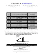
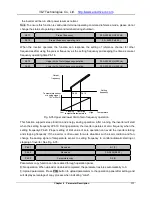
As shown in Fig.6-30 PID Schematic Diagram, the higher the Kp value is, the faster the response is, but
if the Kp value is too high, it may easily generate oscillation and the deviation cannot be eliminated
completely. It can use Ki to eliminate the residual deviation. The higher the Ki value is, the faster the
response of the inverter to the deviation change, but it may easily generate oscillation if the Ki value is
too high. If the system has frequent feedback to the jump, it needs to use Kd because Kd can respond to
the deviation change between the system feedback and the reference quickly. The higher the Kd value is,
the faster the response is, but it may easily generate oscillation if the value is too high.
This function is used to set the sampling cycle of the feedback signal. The lower this parameter value is,
the faster the response of the system to the deviation between the reference and the feedback, but if the
sampling cycle is too fast, the associate requirement for the system PID gain adjustment will be higher,
which may result in system oscillation.
When this function determines the certain level of the deviation between the feedback signal and the
reference signal, it will stop the internal PID adjustment and maintain stable output. Only when the
deviation between the feedback value and the reference value of the close loop exceeds the deviation
limit of P8.07 will the output be updated. Setting the deviation limit needs to take the system control
precision and stability into consideration.
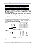
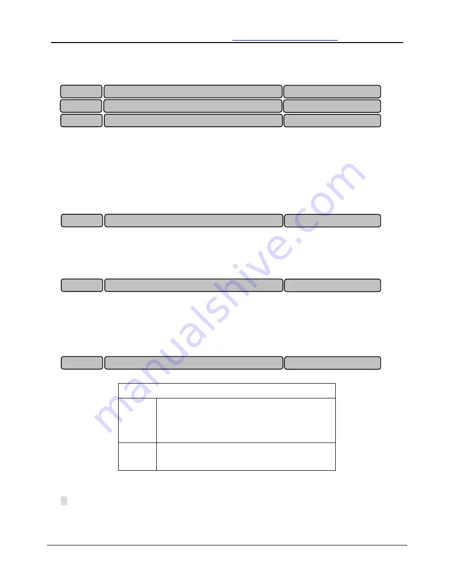
This function determines the specific running mode during the process close loop adjustment.
Display of operation panel
Unit
place
Integration mode
0: Frequency reaches its upper limit and lower limit the
integration adjustment is stopped;
1: Frequency reaches its upper limit and lower limit and the
integration adjustment continues
Tens
place
Output power
0: It must be consistent with the setup running direction.
1: It can be against the setup running direction
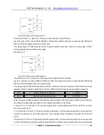
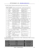
If the output value of the close loop adjustment reaches frequency upper limit or lower limit (P0.13 or
P0.14), there are two actions for selection in the integration section.
0: Stop integration adjustment: the integration value remains unchanged. When there is change
occurring to the deviation between the reference value and the feedback value, the integration value will
follow that change trend.
P8.03
Proportional gain Kp
0.000 ~ 10.000(0.200)
P8.04
Integral gain Ki
0.000 ~ 10.000(0.500)
P8.05
Differential gain Kd
0.000 ~ 10.000(0.000)
P8.06
Sampling cycle
0.001 ~ 30.000 s(0.002s)
P8.07
Deviation limit
0.0 ~ 20.0 %(5.0%)
P8.08
PID adjustment selection
0 ~ 11(10)


