V&T Technologies Co., Ltd.
http://www.ecodrivecn.com
Chapter 3 Wiring of Inverter
29
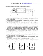
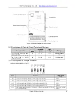
Fig.3-7 Schematic diagram of control board
3.10 Lectotype of Control Circuit Peripheral Devices
Terminal number
Terminal
screw
Tightening
torque
(N·m)
Wire
specification
mm
2
Wire type
+10V, AI1, AI2, AI3, 485+, 485
−,
AO1, AO2, GND
M3
0.5~0.6
0.75
Twinning shielding
cable
+24V, PLC, X1, X2, X3, X4, X5,
X6, X7/DI, COM, Y1, Y2/DO,
COM, RA, RB, RC
M3
0.5~0.6
0.75
Shielding cable
3.11 Description of Jumper Function
Jumper selecting switch in Fig.3-7:
Name
Function
Leave-factory
setting
AI1
I is the current input
(0~20mA), V is the voltage input (0~10V)
0~10V
AI2
I is the current input
(0~20mA), V is the voltage input (0~10V)
0~20mA
AO1
I is the current output
(0~20mA), V is the voltage output (0~10V)
0~10V
AO2
I is the current output
(0~20mA), V is the voltage output (0~10V)
0~20mA
485
485 terminal resistor selection: ON: there is 100
Ω terminal resistor, OFF: there
is no terminal resistor
There is no terminal
resistor
Network cable connection port
Expansion board mounting hole
Jumper selection switch
Drive board
por
Expansion board port
Control circuit terminal
Network cable connection port
Expansion board mounting hole
Jumper selection switch
Drive board port
Expansion board port
Control circuit terminal
Control board grounding


