V&T Technologies Co., Ltd.
http://www.ecodrivecn.com
Chapter 2 Inverter Installation
13
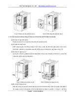
Fig. 2
−
3 Removal of operation panel Fig.2
−
4 Mounting of operation panel
2.3.2 Removal and Mounting of Covers of Inverter with Plastic Enclosure
Removal of operation panel
Please refer to 2.3.1 removal and mounting of operation panel.
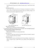
Removal of lower cover
After removing the mounting screws of the cover, press the left and right sides of the cover
forcefully in direction 1 and at the same time lift the cover in direction 2, as shown in Fig. 2
−
5.
Removal of upper cover
As shown in Fig.2
−
6, press the left and right sides of the cover forcefully in direction 1, and at the
same time lift the cover in direction 2.
Fig.2
−
5 Removal of lower cover Fig.2
−
6 Removal of upper cover
Mounting of upper cover
After the wiring of main circuit terminals and control circuit terminals, insert the upper claw grab of
the upper cover into the groove of the inverter body, as shown in position 1 in Fig.2
−
7, and then


