V&T Technologies Co., Ltd.
http://www.ecodrivecn.com
Chapter 2 Inverter Installation
14
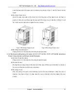
press the lower part of the upper cover in direction 2 as shown in Fig.2
−
7, until the “crack” sound is
heard.
Mounting of lower cover
Insert the upper claw grab on the lower cover into the groove of the upper cover, as shown in
position 1 of Fig.2
−
8, and then press the lower part of the lower cover in direction 2 of Fig.2
−
8, until
the “crack” sound is heard. Now, tighten the cover screws.
Fig.2
−
7 Mounting of upper cover Fig.2
−
8 Mounting of lower cover
Mounting of operation panel
Please refer to 2.3.1 Removal and mounting of operation panel.
2.3.3 Removal and Mounting of Covers of V5
−
H
−4T11G/15L~V
5
−
H
−4T75G/90L and
Above
Power Class Inverter with Sheet-metal Enclosure
Removal of operation panel
Please refer to 2.3.1 Removal and mounting of operation panel.
Removal of cover
Remove the mounting screws on the lower part of the cover, lift the cover in direction 1 as shown in
Fig.2
−
9, and then take out the cover in direction 2.
Mounting of cover
After the wiring of the main circuit terminals and control circuit terminals, cramp the cover in
direction 1 as shown in Fig.2
−
10, press down the cover in direction 2 and then tighten the cover
screws.


