V&T Technologies Co., Ltd.
http://www.ecodrivecn.com
Chapter 6 Parameter Description
105
100%. That is, the use time of the braking unit is fixed to 100.0s
Action voltage of braking unit can be selected by adjusting PA.11. The motor can be stopped rapidly by
energy braking with the appropriate action voltage.
Note: Set PA.09 to 1 when using braking unit. For model selection of braking unit parts and connection,
refer to 1.9 braking unit model selection.
Generally, when inverter produces a failure alarm, the relay will make corresponding indication action.
With this function, the action of error relay terminal can be set under some special conditions.
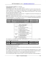
Display of operation panel
Unit place:
Under-voltage failure
0: Disable; 1: Enable
Tens place
Auto reset interval period
0: Disable; 1: Enable
Hundreds
place
Failure locked
0: Disable; 1: Enable
Unit place: Under low-voltage status such as power-up or power failure, choose whether the failure
indication to act or not.
Tens place: When the real failure is not displayed during auto reset period, choose whether the failure
indication to act or not. Refer to PA.21 and PA.22 instructions.
Hundreds place: If failures lock function enabled, when locked failures during last power-failure are
displayed after power-on again, choose whether the failure indication to act or not. Refer to PA.20
instruction.
Overload prealarm function can realize indication of pre-setting overload status or alarm stop.
PA.13 determines overload prealarm detection volume and conditions.
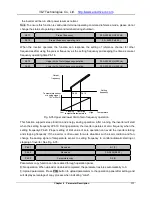
Display of operation panel
Unit place:
Detection volume selection
0: Motor overload prealarm, relative motor
rated current;
1: Inverter overload prealarm, relative
inverter rated current
Tens place
Action selection after overload prealarm
0: Continue to run:
1: Report overload failure and stop
Hundreds
place
Detection conditions selection
0: Detection all the time;
1: Detection only at constant speed
Unit place: Determine overload detection is motor overload prealarm or inverter overload prealarm.
Tens place: Determine inverter continues to run or alarms then stops when the output current exceeds
PA.12
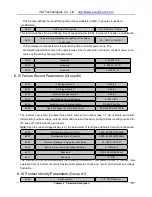
Relay action indication when the inverter is faulty.
0 ~ 111(000)
PA.13
Inverter or motor overload prealarm
0 ~ 111(000)
PA.14
Overload prealarm detection level
20.0 ~ 200.0 %(130.0%)
PA.15
Overload prealarm detection time
0.1 ~ 60.0 s(5.0s)


