53
ED900
02-2020
08125330
dormakaba ED900 Installation Instructions – Double egress door
Chapter 15
4
115 Vac terminal block
5
Ground post
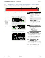
Fig. 15.4.3 115 Vac wiring example
4
5
Fig. 15.4.4 Conduit box installation
15.5.1 Route accessory wiring (Chapter 9)
to active door mounting plate.
1. Route wiring to active door 115 Vac
terminal block side of mounting plate
(Fig. 14.2.1).
TIPS AND RECOMMENDATIONS
Active/inactive door assignments.
Reference Chapter 12, Para. 12.1
for active/inactive door assignments.
15.5 Route accessory wiring to active door mounting plate
2. Accessory wiring, inactive door hinge
side: route wiring to active door 115 Vac
terminal block side of mounting plate.
TIPS AND RECOMMENDATIONS
Accessory wiring will terminate at
ED900 terminal board (Chapter 9).
NOTICE
Installer responsibilities.
Installer responsible for routing
and securing all wiring between
ED900 operators.
15.4.4 Connect customer 115 Vac wiring.
WARNING
Routing and connection of 115 Vac
wiring to ED900 must be
performed by a qualified person!
WARNING
115 Vac branch circuit disconnect or
circuit breaker must be OFF!
1. Route customer wiring to mounting
plate 115 Vac terminal block.
• Standard cover installation; two 115 Vac
connections required.
• Full width cover installation (optional);
one 115 Vac connection required.
CAUTION
115 Vac wiring.
Use copper conductors only!
1. Connect 115 Vac wiring to each terminal
block.
• Terminal block screw tightening torque.
2. Connect earth ground to mounting plate
ground post (s).
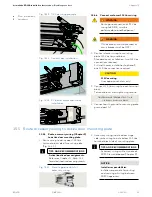
Fig. 15.4.5 PC power cord, conduit box
installation
Fig. 15.5.1 Mounting plate slots for
accessory wiring
TIGHTEN MAINS TERMINAL TO 5-7 in-lb
Use Copper Conductors ONLY


