50
ED900
02-2020
08125330
dormakaba ED900 Installation Instructions – Double egress door
Chapter 15
15.3 Full width cover option – Install cables between mounting plates
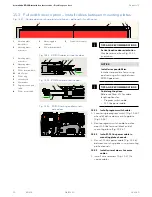
Fig. 15.3.3 ED900 cables at active door
Fig. 15.3.2 ED900 cables at inactive door
1
Mounting plate,
active door
2
Mounting plate,
inactive door
3
115 Vac terminal block
3.1
M3 x 5 screw
4
115 Vac plug
5
Ground stud
6
Wire retainer
7
Program switch and
cable
8
115 Vac power cable
TIPS AND RECOMMENDATIONS
Active/inactive door orientation.
May be reversed from Fig. 15.3.1
orientation.
NOTICE
Installer responsibilities.
Installer responsible for routing
and securing all wiring between
ED900 operators.
TIPS AND RECOMMENDATIONS
Cable length options.
Reference Para. 4.12 for cable
length options for:
• Program switch cable
• 115 Vac power cable
15.3.1 Install program switch cable.
1. Locate single program switch (Fig. 15.3.5)
at end of active door mounting plate
(Fig.15.3.3).
2. Route program switch cable to active
door 115 Vac terminal block end of
mounting plate (Fig. 15.3.4).
15.3.2 Install 115 Vac power cable in
mounting plate channels.
1. Route 115 Vac power cable (Fig. 15.3.6)
between mounting plates using mounting
plate channels.
15.3.3 Install wire retainers to secure
cables.
1. Install wire retainers (Fig. 15.3.7) to
secure cables.
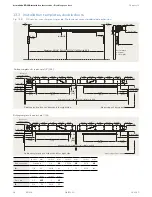
Fig. 15.3.1 Double door mounting plate installation – optional full width cover
1
3
4
5
7
8
6
3.1
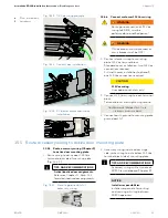
Fig. 15.3.4 ED900 housing and terminals,
active door
1
Mounting plate,
inactive door
2
Mounting plate,
active door
3
Mounting plate
extension
4
115 Vac terminal block
1
2
4
3
5
2
5
7
8
6
5
Conduit box (option)


