2
ED900
02-2020
08125330
dormakaba ED900 Installation Instructions – Double egress door
Table of Contents
Table of contents
2
1
General information
4
1.1
General information
4
1.2
ED900 Arm configurations
4
2
Product description
5
2.1
Product description
5
2.2
Handing of door
5
2.3
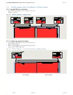
Double egress door installation
configurations 6
3
Safety information
7
4
ED900 Product overview
8
4.1
ED900 push arm system
8
4.2
ED900 pull arm system
8
4.3
ED900 – double egress door configurations
9
4.4
ED900 operator component views
10
5
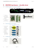
ED900 hardware – double door
12
5.1
ED900 operator and mounting plate
12
5.2
Door decal kit, low energy
12
5.3
Double door communication cable
12
5.4
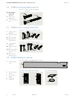
Arm assemblies
13
5.5
Axle extension sleeves and extensions
13
5.6
ED900 mounting plate screw kit
14
5.7
ED900 arm mounting screw kits
14
5.8
ED900 standard cover kit
14
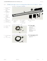
5.9
ED900 full width cover, mounting plate
extension, and cables – option
15
5.10 Key switch panels – option
16
5.11 Push arm door stop - option
16
5.12 Conduit box and wiring kit – options
17
6
Technical data
18
6.1
ED900 Technical data
18
6.2
Operating specifications
19
7
Operational mode overview
19
7.1
ED900 door closer modes
19
7.2
Low energy product
19
8
User interface
20
8.1 Overview
20
8.2
4 button keypad and display
20
8.3
Program and Exit Only switches
21
8.4
Operator status LEDs
21
9
System accessories
22
9.1
System accessory electrical connections
22
9.2
System accessories
22
9.3
ED900 terminal board interfaces
23
10
ED900 door signage
24
10.1 Low energy operator
24
10.2 Door signage, low energy double egress
swing door
25
10.3 Safety Information label, low energy
swing doors
26
Table of contents
11
Recommended tools and torque chart
27
11.1 Recommended tools
27
11.2 Standard tightening torque
27
11.3 Drill bits
27
12
ED900 installation overview
28
12.1 Installation preparation
28
12.2 ED900 operator installation with standard
covers 30
12.3 ED900 operator installation with full
width cover (option)
30
12.4 ED900 operators – assign active door and
inactive door type
30
12.4 ED900 operators – 115 Vac customer
wiring 31
12.5 ED900 operators – program switch
operation 31
12.6 Interconnecting cables
31
13
ED900 installation templates
32
13.2 Installation templates – pull arm
32
13.3 Installation templates – pull as push
35
13.4 Installation templates – push arm
36
13.3 Installation templates, double doors
38
14
ED900 operator and mounting plate
preparation 42
14.1 Remove mounting plate from each ED900
operator 42
14.2 Mounting plate 115 Vac terminal blocks
43
14.3 Options – Customer 115 Vac connection
to terminal blocks
44
14.4 Full width cover option –
ED900 operator preparation and
mounting plate assembly
46
15
ED900 mounting plate and operator
installation 48
15.1 ED900 mounting plate attachment to
jamb and/or wall examples
48
15.2 Install ED900 mounting plate to jamb
and/or wall
49
15.3 Full width cover option – Install cables
between mounting plates
50
15.4 Connect customer 115 Vac to ED900
mounting plate terminal block
52
15.5 Route accessory wiring to active door
mounting plate
53
15.6 Remove protective film strips from each
ED900 operator
54
15.7 Install each ED900 operator onto its
mounting plate
54
15.8 Full width cover option – Install program
switch, active door ED900
55
15.9 Full width cover option – 115 Vac pair
power cable connections
56


