74
ED900
02-2020
08125330
dormakaba ED900 Installation Instructions – Double egress door
Chapter 23
23.1 First commissioning
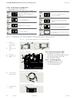
Fig. 23.1.2 Power switch
Fig. 23.1.1 Program switch
2
Power switch
Fig. 22.1.3 4 button keypad,
2 digit display
3
Four button
keypad
4
Two digit display
23 Single door first commissioning
1
Program switch,
3 position
o
2
4
3
> 3s Reset
< 3s Quit
> 3s
PRG
< 3s
LEARN
Fact-Setup
> 3s
> 8s
Conditions prior to commissioning.
1. ED900 operators are installed.
2. Standard push arms or arm with tracks are
installed.
3. 115 Vac branch circuit to operators is energized.
4. Operator motors are cold.
CAUTION
Motors must be cold for commissioning!
Step 1
Program switch to CLOSE position.
Step 2
Power switch to ON position.
System check.
• Series of letters and numbers
rapidly displayed.
Control unit self check.
• Two segments jumping back
and forth.
Horizontal dashes move up and
down.
Step 3
Press 4 button keypad
down button
.
While 2 digit display segments
move up and down, letters and
numbers will change if required
to display correct orientation.
Display scrolls:
• Device ID (Ed 900)
• Firmware version
(format F x x x x)
Program mode display.
Program mode will be displayed
indicating system requires further
parameter settings.
TIPS AND RECOMMENDATIONS
If pressing down button (Step 3) does not
result in desired display orientation,
return to Step 2, turn power button off, then
on to repeat commissioning steps.
23.1.1 First commissioning.
Steps in Para. 23.1 through Para. 23.4 must be
completed for each ED900 operator.
TIPS AND RECOMMENDATIONS
Accessory wiring.
Termination of accessory wiring to the ED900
active door operator should be done only after
operator commissioning is completed and
learning cycle is performed for each door.
Reference Chapter 25 for accessory wiring.


