58
ED900
02-2020
08125330
dormakaba ED900 Installation Instructions – Double egress door
Chapter 16
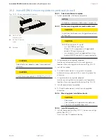
Fig. 16.2.5 Push arm assemblies for installation
16.2.2 Attach drive arm to operator.
CAUTION
Door must be fully closed!
WARNING
Use caution when working in
proximity of door and push arm!.
CAUTION
ED operator axle zero position.
In order to mount the drive arm in
the correct position, the axle must
be brought to the zero position.
1. Set ED operator spring preload to
approximately ten clockwise rotations.
• Axle rotates to the zero position.
TIPS AND RECOMMENDATIONS
Reference Chapter 19, Operator
spring tension.
2. Insert axle extension into drive arm.
3. Move arm to ED900, inserting arm into
operator spindle at a 90⁰ angle
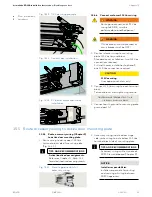
(Fig. 16.2.5).
4. Insert M8 SHCS through drive arm and
axle extension. Thread SHCS into
ED900 spindle and tighten.
CAUTION
Use torque wrench with hex key
socket to tighten SHCS to
17 ft-lb [23 Nm]
16.2.3 Drill two holes in door for
adjustment arm shoe.
Installation templates (Chapter 13)
document location of shoe on door.
1. Drill two holes in door for adjustment
arm shoe.
• Fastener type based on door material.
TIPS AND RECOMMENDATIONS
Reference Chapter 5, Accessory
kits, for arm fasteners.
16.2.4 Secure adjustment arm assembly
to door.
1. Fasten adjustment arm assembly to
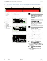
door (Fig. 16.2.6).
1
Drive arm
4
Adjustment arm
11 1/4"[285]
5
Adjustment arm
tube 12 1/4" [311]
6
Shoe
7
M6 x 10 mm flanged
button head screw
8
Ball head
9
Adjustment arm,
17 3/4" [450]
10
Adjustment arm
tube, 17 3/4" [450]
11
ED900 spindle
12
Axle extension sleeve
1
5,10
11
12
6
4,9
Fig. 16.2.6 Arm assemblies attached to
door and ED900
1
Drive arm
6
Shoe
9
Adjustment arm,
17 3/4" [450]
10
Adjustment arm
tube, 17 3/4" [450]
Fig. 16.2.3 Drive arm
1
Drive arm
2
Socket
3
Arm axle sleeve
1
9,10
6
1
2
3
Fig. 16.2.4 Drive arm axle extension installation
1
Drive arm
12
Axle extension sleeve
13
Axle extension
14
M8 x ___ SHCS
1
12
13
14


