41
ED900
02-2020
08125330
dormakaba ED900 Installation Instructions – Double egress door
Chapter 13
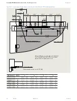
Fig. 13.3.4 Push version with arm, mounting on opposite hinge side, Professional cover, standard axle extension
Inches
mm
Inches
mm
Inches
mm
Inches
mm
Axle extension
Standard
3/4
20
1 3/16
30
2 3/8
60
A
3/8
9
1 1/8
29
1 17/32
39
2 23/32
69
ED 100 =
ED 250 =
5/8”
[15]
5/8”
[15]
5 7/8”
[150]
9 5/8”
[245]
1 31/32”
[50]
A + 1 5/16”
[33]
EN 7 =
9 7/8”
[250]
EN 7 =
12 13/16”
[325]
1 31/32”
[50]
9 5/8”
[245]
5 7/8”
[150]
EN 7 =
9 7/8”
[250]
EN 7 =
12 13/16”
[325]
5 1/8” [130]
2 3/4” [70]
A
1 5/16”
[33]
0 – 11 13/16”
[0 – 300]
0 – 19 11/16”
[0 – 500]
Drilling template: arm EN 7
Center of
operator axle
3 15/16”
[100]
4 3/4”
[120]
4 3/4”
[120]
4 3/4”
[120]
3 3/4”
[95]
3/8” [9]
1 3/4” [45]
8 1/8” [206]
9 7/8” [250]
12 13/16” [325]
1 31/32
[50]
12 13/16” [325]
1 31/32
[50]
5 11/16”
[145]
2 1/2” [63]
1 1/4” [31.5]
8 1/8” [206]
9 7/8” [250]
Minimum 55 1/8” [1400], 57 1/16” [1450] with ESR
1 5/16”
[33]
3 15/16”
[100]
4 3/4”
[120]
4 3/4”
[120]
4 3/4”
[120]
3 3/4”
[95]
Ø1/4”
[6,6]
Ø1/4”
[6,6]
Bottom edge of reveal
Cable entry location on either the left or right side.
Drilling template: arm EN 3-6
1 3/4” [45]
Center of
operator axle
2 1/2” [63]
1 1/4” [31.5]
4 3/16” [106]
5 7/8” [150]
9 5/8”
[245]
Ø1/4”
[6,6]
3 15/16”
[100]
4 3/4”
[120]
4 3/4”
[120]
4 3/4”
[120]
3 3/4”
[95]
1 31/32
[50]
1 5/16”
[33]
Minimum 55 1/8” [1400], 57 1/16” [1450] with ESR
Ø1/4”
[6,6]
3 15/16”
[100]
4 3/4”
[120]
4 3/4”
[120]
4 3/4”
[120]
3 3/4”
[95]
1 31/32
[50]
9 5/8”
[245]
4 3/16” [106]
5 7/8” [150]
3/8” [9]
1 3/4” [45]
Bottom edge of reveal
Cable entry location on either the left or right side.
Minimum 55 1/8” [1400], 57 1/16” [1450] with ESR


