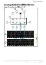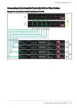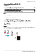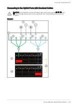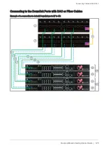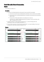
Connecting Cables to MHO-140
Quantum Maestro Getting Started Guide | 126
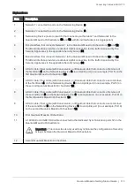
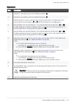
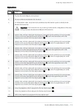
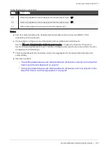
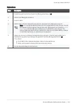
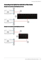
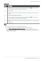
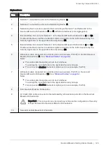
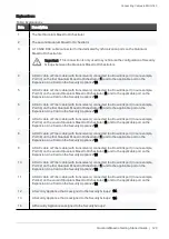
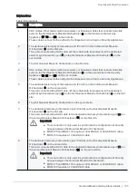
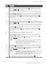
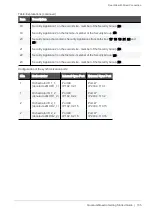
Explanations:
Item
Description
1
Network 1 connected to ports on the Networking Device (
3
).
2
Network 2 connected to ports on the Networking Device (
3
).
3
Networking Device (router or switch) that connects your Network 1 and Network 2 to the
Quantum Maestro Orchestrators (
6
and
8
) with Bond interfaces (Link Aggregation).
4
Bond interface that connects Network 1 to the Quantum Maestro Orchestrators (
8
and
10
).
This Bond interface provides a redundant Uplink connection for the traffic inspected by the
Security Appliances in the applicable Security Group (
31
).
5
Bond interface that connects Network 2 to the Quantum Maestro Orchestrators (
8
and
10
).
This Bond interface provides a redundant Uplink connection for the traffic inspected by the
Security Appliances in the applicable Security Group (
30
).
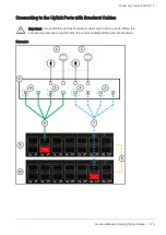
6
A Breakout cable connected to an Uplink port (in our example, Port 49) on the first Quantum
Maestro Orchestrator (
8
). See
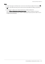
Notes:
n
This cable splits the Uplink port into four interfaces.
You assign the new interfaces to the applicable Security Groups.
n
This connection disables the bottom Uplink port (in our example, Port 50).
7
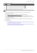
A Breakout cable connected to an Uplink port (in our example, Port 55) on the second
Quantum Maestro Orchestrator (
10
). See
.
Notes:
n
This cable splits the Uplink port into four interfaces.
You assign the new interfaces to the applicable Security Groups.
n
This connection disables the bottom Uplink port (in our example, Port 56).
8
First Quantum Maestro Orchestrator.
9
A 10 GbE DAC cable connected to the dedicated Synchronization ports 48 on the Quantum
Maestro Orchestrators.
Important - This connection is only used to synchronize the configuration of Security
Groups between the Quantum Maestro Orchestrators.
10
Second Quantum Maestro Orchestrator.

