background image

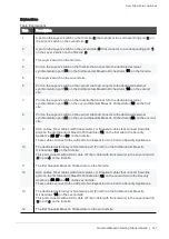
Dual Site with Direct Connection

Quantum Maestro Getting Started Guide   |   141

Step

Instructions

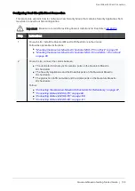
1

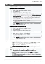
On the new site, install the Quantum Maestro Orchestrators in their racks.
Follow the applicable instructions:

n

"Mounting the Quantum Maestro Orchestrator MHO-175 in a Rack" on page 53

n

"Mounting the Quantum Maestro Orchestrator MHO-140 and MHO-170 in a Rack"
on page 68

2

On the new site, connect the cables between:

n

The dedicated internal synchronization ports on the Quantum Maestro
Orchestrators.

n

The Security Appliances and the Downlink ports on the Quantum Maestro
Orchestrators.

n

The production traffic networks and the Uplink ports on the Quantum Maestro
Orchestrators.

Follow:

n

"Connecting Two Quantum Maestro Orchestrators for Redundancy" on page 87

.

n

"Connecting Cables to MHO-175" on page 98

n

"Connecting Cables to MHO-170" on page 109

n

"Connecting Cables to MHO-140" on page 121

.

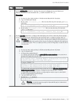
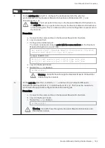
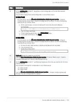
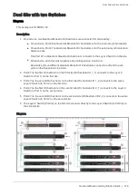
3

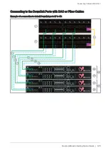
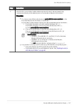
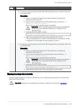
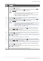
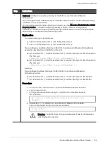
On each site, connect fiber cables (with transceivers) or DAC cables between the
dedicated external synchronization ports on the Quantum Maestro Orchestrator.

Procedure

n

You must connect fiber cables between ports with the same numbers on the
Quantum Maestro Orchestrators on each site.
Connect fiber cables between these pairs of Quantum Maestro Orchestrators:

1. The first Orchestrator on the first site (Orchestrator ID 1_1).

The first Orchestrator on the second site (Orchestrator ID 2_1).
Connect ports with the same numbers.

2. The second Orchestrator on the first site (Orchestrator ID 1_2).

The second Orchestrator on the second site (Orchestrator ID 2_2).
Connect ports with the same numbers.

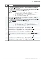
Best Practice:

l

On MHO-175 and MHO-170, use Ports 31 on the Quantum Maestro
Orchestrators on each site.

l

On MHO-140, use Ports 47 on the Quantum Maestro Orchestrators
on each site.

l

Do not use ports with the configured type "

management

".

n

It is possible to use any port for external synchronization, except these ports:

l

The ports already used for the internal synchronization.

l

The disabled ports, if you used breakout cables. See

"Splitting the Ports with

Breakout Cables" on page 82

.

Summary of Contents for QUANTUM MAESTRO

Page 1: ... Classification Protected 11 November 2021 QUANTUM MAESTRO Getting Started Guide ...

Page 2: ...precaution has been taken in the preparation of this book Check Point assumes no responsibility for errors or omissions This publication and features described herein are subject to change without notice RESTRICTED RIGHTS LEGEND Use duplication or disclosure by the government is subject to restrictions as set forth in subparagraph c 1 ii of the Rights in Technical Data and Computer Software clause...

Page 3: ... against new and evolving attacks Certifications For third party independent certification of Check Point products see the Check Point Certifications page Quantum Maestro Getting Started Guide Latest Version of this Document in English Open the latest version of this document in a Web browser Download the latest version of this document in PDF format Feedback Check Point is engaged in a continuous...

Page 4: ... Administration Guides 12 September 2020 Improved n Formatting and document layout Updated n Introduction on page 16 n MHO 170 Front Panel on page 26 n MHO 140 Rear Panel on page 30 n Ports on page 45 n Dual Site on page 131 n Connecting Two Quantum Maestro Orchestrators for Redundancy on page 87 n Thermal Threshold Definitions on page 183 25 September 2019 Updated n Fan Status LED on page 34 Adde...

Page 5: ...trators for Redundancy on page 87 n Splitting the Ports with Breakout Cables on page 82 n MHO 170 Specifications on page 181 n MHO 140 Specifications on page 182 01 July 2019 Added this information was moved from the Maestro Administration Guide n Connecting Cables to Quantum Maestro Orchestrators on page 81 Updated n Document design 28 February 2019 First release of this document ...

Page 6: ... MHO 140 Front Panel 29 MHO 140 Rear Panel 30 LEDs 31 LED Notifications 31 System Status LED 32 Fan Status LED 34 Power Supply Unit Status LEDs 36 Bad Port LED 39 Port LEDs 39 Ports 45 Reset Button 49 Replacing Power Supply Units 50 Replacing Fan Units 52 Mounting the Quantum Maestro Orchestrator MHO 175 in a Rack 53 Mounting the Quantum Maestro Orchestrator MHO 140 and MHO 170 in a Rack 68 Connec...

Page 7: ...th Breakout Cables 111 Connecting to the Uplink Ports with DAC or Fiber Cables 112 Connecting to the Uplink Ports with Breakout Cables 115 Connecting to the Downlink Ports with DAC or Fiber Cables 118 Connecting Cables to MHO 140 121 Connecting to the Management Ports with DAC or Fiber Cables 121 Connecting to the Uplink Ports with DAC or Fiber Cables 123 Connecting to the Uplink Ports with Breako...

Page 8: ...Table of Contents Quantum Maestro Getting Started Guide 8 MHO 170 and MHO 140 187 What is the Next Step 188 ...

Page 9: ...to connect to network devices switches routers or servers Downlink See Downlink Ports Downlink Ports Interfaces on the Maestro Hyperscale Orchestrator used to connect to Check Point Security Appliances You use DAC cables Fiber cables with transceivers or Breakout cables to connect between the Downlink ports and Security Appliances The Check Point Management traffic policy logs synchronization and ...

Page 10: ...nections are only synchronized to backup Security Appliances in the Security Group HyperSync makes sure each connection flow has a backup within the Security Group M Maestro Hyperscale Orchestrator A scalable Network Security System that connects multiple Check Point Security Appliances into a unified system Acronym MHO Management Interface Interface on Gaia computer through which users connect to...

Page 11: ...s Security Appliance in a Security Group has one IPv4 address and represents all assigned Security Appliances as one entity Shared Management Feature that allows to assign the same Management Port interface ethX MgmtY on a Maestro Hyperscale Orchestrator to different Security Groups The assigned Management Port has a different IP address and a different MAC address in each Security Group to which ...

Page 12: ... Interfaces on the Maestro Hyperscale Orchestrator used to connect to external and internal networks Gaia Operating System shows these interfaces in Gaia Portal and in Gaia Clish SmartConsole shows these interfaces in the corresponding SMO Security Gateway object ...

Page 13: ...o not operate this equipment in an area with an ambient temperature that exceeds the recommended maximum 45 C 113 F To guarantee proper cooling allow at least 8 cm 3 inches of clearance around the ventilation openings Stacking the Chassis Do not stack the Chassis on any other equipment If the Chassis falls it can cause bodily injury and equipment damage Redundant Power Supply Connection Electrical...

Page 14: ...isposal Dispose of this equipment in compliance with all national laws and regulations Installation Codes Install this equipment according to the latest version of the country national electrical codes For North America see the applicable requirements in the US National Electrical Code and the Canadian Electrical Code Battery Replacement Warning Replace only with UL Recognized battery certified fo...

Page 15: ... the slide rail mounted equipment as a shelf or a work space The rails are not intended for sliding the unit away from the rack It is for permanent installation at final resting place only not used for service and maintenance WEEE Directive According to the WEEE Directive 2002 96 EC all waste electrical and electronic equipment EEE should be collected separately and not disposed of with regular ho...

Page 16: ...ally distributes traffic between the Security Appliances assigned to Security Groups n Ability to connect more Security Appliances and use their resources easily in the existing Security Groups Overview Quantum Maestro Orchestrator 1U systems are ideal for leaf and spine data center network solutions that provide maximum flexibility with port speeds from 1 Gbit sec to 100 Gbit sec per port and por...

Page 17: ...t head Phillips screws with a round patch 6 32x1 4 100 Deg Patch 360 Cables and Adapters n 2 power cables Type C13 C14 n 2 cable retainers n 1 DB9 to RJ45 serial console cable n 1 DAC cable 3m Documentation n Quick Start Guide n Port Mapping n User license agreement Table Shipping Carton Contents Notes n DB9 connectors are also known as DE9 connectors n Before installing your new Quantum Maestro O...

Page 18: ...4 76 Bpps l MHO 140 Throughput of up to 1280 Gbit sec and processing capacity up to 2 97 Bpps n Flat latency in the cut through mode l MHO 175 425 ns l MHO 170 300 ns l MHO 140 300 ns n Speeds of 1 10 40 and 100 GbE n Dynamically shared flexible packet buffering l MHO 175 42 MB l MHO 170 16 MB l MHO 140 16 MB n Lowest power under 5 W per 100 GbE port n Enhanced scalability n 1 1 hot swappable powe...

Page 19: ...QSFP28 use QSFP to SFP breakout cables 8 1 28 Tbit sec Quantum Maestro Orchestrator supports different interfaces and speed rates when you use QSFP to SFP adapters or hybrid cables For more information see Splitting the Ports with Breakout Cables on page 82 Ports Power Supply Units and Fan Units Orchestrator Model MGMT Ports USB Ports Console Ports PSUs Fans MHO 175 1 on the front panel 1 on the f...

Page 20: ...nal and internal networks 8 RJ45 port for Console connection 3 Ports 17 30 are the Downlink ports lead to Security Appliances 9 Port 32 is the Synchronization port on the same Site leads to the peer Orchestrator on the same Site 4 Port 31 is the Synchronization port in Dual Site leads to the peer Orchestrator on another Site In the Split mode the 4th split is Sync and other splits are Downlinks 10...

Page 21: ...Groups lead to the Check Point Management Server 6 System Health LEDs 2 Ports 3 16 are the Uplink ports 40 Gbps 100 Gbps lead to external and internal networks 7 Port 30 is the Synchronization port in Dual Site leads to the peer Orchestrator on another Site 3 Ports 17 29 and 31 are the Downlink ports lead to Security Appliances 8 Port 32 is the Synchronization port on the same Site leads to the pe...

Page 22: ...s the Synchronization port in Dual Site leads to the peer Orchestrator on another Site 3 Ports 5 26 are the Uplink ports 1 Gbps 10 Gbps lead to external and internal networks 9 Management port Mgmt1 for the Gaia OS on the Orchestrator 4 Ports 27 47 are the Downlink ports lead to Security Appliances 10 Management port Mgmt2 for the Gaia OS on the Orchestrator 5 Ports 49 55 are the Uplink ports 40 G...

Page 23: ... n Check Point Management Servers n Clients from which you configure the Gaia Operating System Gaia Portal and Gaia Clish on the Security Appliances connected to the Downlink ports 3 Important It is possible to use only this port 2 40 Gbps 100 Gbps Uplink ports 2 to 16 colored gray To these ports you connect your external traffic and internal traffic networks You use DAC or Fiber cables with trans...

Page 24: ...ntum Maestro Orchestrators MHO 175 for redundancy on the same site 10 Button to select indication states for the splitting control LEDs See MHO 175 Splitting Options on page 83 11 Splitting control LEDs that show the indication state for Port LEDs n State of which port to show without a split cable n State of which split port to show in 1 to 2 split or 1 to 4 split See MHO 175 Splitting Options on...

Page 25: ...5 MHO 175 Rear Panel Item Description 1 First Power Supply Unit See Replacing Power Supply Units on page 50 2 Fan Units 1 2 3 4 5 and 6 from left to right See Replacing Fan Units on page 52 3 Second Power Supply Unit See Replacing Power Supply Units on page 50 ...

Page 26: ...gement Servers n Clients from which you configure the Gaia Operating System Gaia Portal and Gaia Clish on the Security Appliances connected to the Downlink ports 4 Important It is possible to use only these ports 3 40 Gbps 100 Gbps Uplink ports 3 to 16 colored blue To these ports you connect your external traffic and internal traffic networks You use DAC or Fiber cables with transceivers 4 Downlin...

Page 27: ...J45 port with the label CONSOLE See Console Port on page 48 To this port you connect a client from which you configure the Gaia Operating System on the Quantum Maestro Orchestrator in Gaia Clish Notes n It is possible to connect DAC or Fiber cable with transceivers to each port from 1 to 32 n It is possible to connect Breakout cables only to the top ports In this case the bottom ports are disabled...

Page 28: ... 28 MHO 170 Rear Panel Item Description 1 First Power Supply Unit See Replacing Power Supply Units on page 50 2 Fan Units 1 2 3 and 4 from left to right See Replacing Fan Units on page 52 3 Second Power Supply Unit See Replacing Power Supply Units on page 50 ...

Page 29: ...ports 5 to 26 colored blue To these ports you connect your external traffic and internal traffic networks You use DAC or Fiber cables with transceivers 4 Downlink ports 27 to 47 colored orange To these ports you connect your Check Point Security Appliances You use DAC or Fiber cables with transceivers 5 40 Gbps 100 Gbps Uplink ports 49 to 56 colored yellow To these ports you connect your external ...

Page 30: ...ator Gaia Portal and Gaia Clish 5 RJ45 port labeled 1 through which it is also possible to configure the Gaia Operating System on the Quantum Maestro Orchestrator Gaia Portal and Gaia Clish 6 Reset button labeled R See Reset Button on page 49 7 RJ45 port with the label CONSOLE See Console Port on page 48 To this port you connect a client from which you connect to the Gaia Operating System on the Q...

Page 31: ...rmal Condition System Status LED on the next page Shows the health of the Quantum Maestro Orchestrator Steady green or flashing green during boot Fan Status LED on page 34 Shows the health of the Fan Units Steady green Power Supply Unit Status LEDs on page 36 Shows the health of the Power Supply Units Steady green Bad Port LED on page 39 Lights up when the Quantum Maestro Orchestrator detects an e...

Page 32: ... 32 System Status LED System Status LED Location Orchestrator Model Location of the System Status LED On the front panel On the rear panel MHO 175 N A MHO 170 N A MHO 140 Note On MHO 140 this LED is located on the front panel and the rear panel ...

Page 33: ...r example the Orchestrator overheated has a corrupted firmware there is a CPU error Check environmental conditions room temperature It may take up to five minutes to power on the Orchestrator If the System Status LED is lit steady red for five minutes after you started the Orchestrator unplug the Orchestrator and contact Check Point Support Flashing for more than five minutes Software did not boot...

Page 34: ...the rear panel MHO 175 N A MHO 170 N A MHO 140 Fan Status LED Behavior Front Panel Important Currently FAN LEDs are always off LED Behavior Instructions Action Required Steady green All fans are up and running normally None Steady red or amber Error One or more fan units are not operating properly Replace the faulty fan units Off The Orchestrator boots None ...

Page 35: ...s Action Required Steady green A specific fan unit is operating None Steady red or amber A specific fan unit is missing or not operating properly Replace the faulty fan unit Off The Orchestrator boots None Important With the fan unit removed power pins are accessible within the module cavity Do not insert tools or body parts into the fan unit cavity ...

Page 36: ...y Units To provide power redundancy there are two power supply inlets in Quantum Maestro Orchestrators A Quantum Maestro Orchestrator can operate with only one PSU connected In case the PSU is faulty it is possible to add a second PSU to support hot swap ability Each PSU has a single two color LED on the right side of the PSU that indicates the status of the PSU Orchestrator Model Location of the ...

Page 37: ...he left side and the secondary PSU is located on the right side of the Quantum Maestro Orchestrator The PSU Status LEDs are located on the PSUs themselves Each PSU has one LED of its own Power Supply Unit LED Rear Panel in MHO 175 Power Supply Unit LED Rear Panel in MHO 170 Power Supply Unit LED Rear Panel in MHO 140 ...

Page 38: ...lly None Flashing green at 1Hz AC is present only 12VSB on PSU off or PSU in Smart On state Contact Check Point Support Steady read or amber AC cord is unplugged or AC power is lost while the second PSU still has AC input power Plug in the AC cord to the faulty PSU Make sure there is the AC power PSU failure voltage current temperature or fan Check the voltage of your AC power If voltage is OK con...

Page 39: ...d connector Check error counters to identify the ports For more information see the Maestro Administration Guide for your version Replace the cables connected to these ports Port LEDs Port LEDs on are located on the front panel Port LEDs on MHO 175 In MHO 175 all port LEDs are located on the right side There are 32 LEDs that correspond to the 32 physical ports You can connect 1 to 4 breakout cable...

Page 40: ...Security Groups Example When you connect a breakout cable to the top port 8 interface eth1 29 you get Port Number on the Front Panel Interface Name in Gaia OS Port Name in Gaia OS 8 eth1 29 Port 1 8 1 eth1 30 Port 1 8 2 eth1 31 Port 1 8 3 eth1 32 Port 1 8 4 Note For more information about the ports and interface names in Gaia see Quantum Maestro Orchestrator Ports and Gaia OS Interfaces on page 17...

Page 41: ...ce eth1 29 then in this LED indication mode 1 the port LED 8 shows the state of the interface eth1 29 Port 1 8 1 2 Only the second LED from the left is lit 2 Port LEDs show the state of the second split port of the physical port Example If you connect a breakout cable to port 8 interface eth1 29 then in this LED indication mode 2 the port LED 8 shows the state of the interface eth1 30 Port 1 8 2 3...

Page 42: ...is connected The traffic is flowing in at list one of the split ports None Flashing amber Undetermined state Select another LED Indication Mode 1 2 3 or 4 Port LED Behavior in the LED Indication Modes 1 2 3 or 4 LED Behavior Port State Action Required Off Link is down Check the cable Steady green Link is up in the corresponding split port but the traffic is not flowing in that split port None Flas...

Page 43: ...orts is indicated by two LEDs Example Port LED Behavior LED Behavior Port State Action Required Off Link is down Check the cable Steady green Link is up but there is no traffic None Flashing green Link is up and the traffic is flowing None Flashing amber A problem with the link Check the cable and replace if needed ...

Page 44: ... the upper LEDs operate only when the port is split with a breakout cable n When the upper port is split to four interfaces its bottom port is disabled n If the ports run at a 100 GbE or 40 GbE speed each the two lower LEDs 2 and 4 light in green Port LED Behavior LED Behavior Port State Action Required Off Link is down Check the cable Steady green Link is up but there is no traffic None Flashing ...

Page 45: ...ore information see the l Quantum Maestro Quick Start Guide for MHO 175 and MHO 140 l Quantum Maestro Quick Start Guide for MHO 170 and MHO 140 n For more information see the Quantum Maestro Quick Start Guide for MHO 170 and MHO 140 n In MHO 140 the second MGMT port is not configured with an IP address n To change the default IP address 1 Connect to the Quantum Maestro Orchestrator over the RJ45 c...

Page 46: ...Ports Quantum Maestro Getting Started Guide 46 Orchestrator Model Location of the MGMT Port On the front panel On the rear panel MHO 175 N A MHO 170 N A MHO 140 N A ...

Page 47: ...possible to connect to this interface an external USB storage device for software upgrade or file management Do not use excessive force when inserting or removing the USB storage device to and from the connector Orchestrator Model Location of the USB Port On the front panel On the rear panel MHO 175 N A MHO 170 N A MHO 140 N A ...

Page 48: ... Quantum Maestro Orchestrator Orchestrator Model Location of the RS232 Console Port On the front panel On the rear panel MHO 175 N A MHO 170 N A MHO 140 N A You use this port for initial configuration and debugging Use these settings to connect a PC to the RJ45 console port Parameter Setting Baud Rate 115200 Data bits 8 Stop bits 1 Parity None Flow Control None ...

Page 49: ... reboot of the Quantum Maestro Orchestrator use a flat object to push the reset button Do not use a sharp pointed object such as a needle or a push pin to press the reset button Orchestrator Model Location of the Reset Button On the front panel On the rear panel MHO 175 N A MHO 170 N A MHO 140 N A ...

Page 50: ...ator s internal temperature See n Airflow in MHO 175 on page 54 n Airflow in MHO 170 and MHO 140 on page 69 Removing a Power Supply Unit Important n Before you remove one of the PSUs make sure that 1 The System Status LED is lit in steady green see System Status LED on page 32 2 The Power Supply Unit Status LEDs on the PSU that you leave in the Orchestrator are lit in steady green see Power Supply...

Page 51: ...eel a slight resistance 4 Continue to press the PSU until it seats completely The PSU latch snaps into place This confirms the proper installation 5 Connect the power cord to the PSU connector 6 Insert the other end of the power cord into an outlet of the correct voltage 7 These should light up in green color 1 The indicator on the PSU 2 The Power Supply Unit Status LED see Power Supply Unit Statu...

Page 52: ...sh the latch release with your thumb 3 Pull out the fan unit from the Quantum Maestro Orchestrator As you pull out the fan unit its status LEDs turns off see Fan Status LED on page 34 Installing a Fan Unit Step Instructions 1 Make sure the mating connector of the new fan unit is free of any dirt and obstacles 2 Insert the fan unit end into the opening 3 Slide in the fan unit until you feel a sligh...

Page 53: ...ation to maintain good airflow at ambient temperature n Unless otherwise specified Check Point products are designed to work in an environmentally controlled data center with low levels of gaseous and dust particulate contamination The installation procedure for the Quantum Maestro Orchestrator involves these phases Phase Instructions 1 Make sure that none of the shipping carton contents is missin...

Page 54: ...planned with the same airflow direction n All fan units in the same rack need to have the same air flow direction A mismatch in the air flow affects the heat dissipation in the rack Static Rail Kit for MHO 175 The Quantum Maestro Orchestrators are sold with the static rail kit Important At least two people are required to mount the Quantum Maestro Orchestrator safely in the rack Installation Rail ...

Page 55: ...crews with a round patch Head 100 Degree Type I Size 6 32 Length 1 4 inch Legend Notes n You use the Phillips flat head screws F to secure the rack mount rails A to the Quantum Maestro Orchestrator n You use the Phillips flat head screws F to secure the rack mount rail ears C to the Quantum Maestro Orchestrator n You use the cage nuts D and Phillips pan head screws E to secure the rack mount rails...

Page 56: ...o place the Quantum Maestro Orchestrator review these points n Make sure the Quantum Maestro Orchestrator air flow is compatible with your installation selection It is important to keep the airflow within the rack in the same direction n Note that the part of the Quantum Maestro Orchestrator to which you choose to attach the rails determines the Quantum Maestro Orchestrator s adjustable side The Q...

Page 57: ...ide 57 Installation Option 1 Attaching the mount rail ears C near the rear panel Installation in short racks 43 58 cm 16 9 22 8 inches Important In short racks the designated windows in the rack mount rails must align with the ventilation openings on the sides of the Quantum Maestro Orchestrator ...

Page 58: ...Mounting the Quantum Maestro Orchestrator MHO 175 in a Rack Quantum Maestro Getting Started Guide 58 Installation in standard racks 58 80 cm 19 6 31 5 inches ...

Page 59: ...uantum Maestro Orchestrator MHO 175 in a Rack Quantum Maestro Getting Started Guide 59 Installation Option 2 Attaching the mount rail ears C near the front panel Installation in short racks 43 58 cm 16 9 22 8 inches ...

Page 60: ...bles that cannot bend within the rack or in case more space is needed for cable bending radius it is possible to recess the connector side or the rear panel side by 8 9 cm 3 5 inches by optional placement of the Quantum Maestro Orchestrator s rails n If you mount the rack blades as depicted in Installation Option 2 above it lets you slide the PSUs and Fan Units in and out easier ...

Page 61: ...each side of the Quantum Maestro Orchestrator Important You must use one screw on each side 3 Tighten the screws with a torque of 1 5 0 2 Nm Step 2 Attaching the Rack Mount Ears Step Instructions 1 Attach the left and right rack mount rail ears C to the left and right sides of the Quantum Maestro Orchestrator 2 Gently push the pins on the sides through the slider key holes until the rack mount rai...

Page 62: ...ge nuts D in the desired 1U slots of the rack Notes n The red frame on the image denotes the Quantum Maestro Orchestrator inside the rack n Install four cage nuts on each side of the Quantum Maestro Orchestrator n Each rack 1U unit consists of three holes Install the cage nuts vertically so that its ears engage the top and bottom holes only Example ...

Page 63: ...he Rack While your installation partner is supporting the Quantum Maestro Orchestrator perform these steps Step Instructions 1 Attach the rack mount blades B to the back side FRU side of the rack at the level of the designated cage nuts 2 Insert four Phillips pan head screws E in the designated cage nuts 3 Do not tighten the screws yet Example ...

Page 64: ...il ears C face the rack s posts correctly 2 Slide the rack mount rails A inside the rack mount blades B to fit your rack s depth 3 Attach the rack mount rail ears C to the rack s posts 4 Use the four Phillips pan head screws E to secure each rack mount rail ear C to each side of the rack 5 Do not tighten the screws yet Example Step 6 Tightening the Screws While your installation partner is support...

Page 65: ...dicator corresponding to each data port light up when the physical connection is established When a logical connection is made the relevant port LED lights up To remove a cable disengage the locks and slowly pull the connector away from the port receptacle The LED indicator for that port turns off when the cable is unplugged Note For more information about Port LEDs see Port LEDs on page 39 Do not...

Page 66: ...the Quantum Maestro Orchestrator If after five minutes the System Status LED is lit in red color unplug the power cords and contact Check Point Support 4 Check the status of the Quantum Maestro Orchestrator LEDs see LED Notifications on page 31 All of the LEDs must show status lights that are consistent with normal operation initially flashes and then lights in a steady color Example Important n A...

Page 67: ...OS Log in to the Quantum Maestro Orchestrator Gaia Portal or Command Line with these default credentials n Username admin n Password admin See the Quantum Maestro Quick Start Guide in the shipping carton Best Practice Change the default password Note There is no Gaia First Time Configuration Wizard on Quantum Maestro Orchestrators ...

Page 68: ...lation to maintain good airflow at ambient temperature n Unless otherwise specified Check Point products are designed to work in an environmentally controlled data center with low levels of gaseous and dust particulate contamination The installation procedure for the Quantum Maestro Orchestrator involves these phases Phase Instructions 1 Make sure that none of the shipping carton contents is missi...

Page 69: ...l fan units in the same rack need to have the same air flow direction A mismatch in the air flow affects the heat dissipation in the rack Static Rail Kit for MHO 170 and MHO 140 The Quantum Maestro Orchestrators are sold with the static rail kit Important At least two people are required to mount the Quantum Maestro Orchestrator safely in the rack Installation Rail Kit Rack Size and Rack Depth Ran...

Page 70: ...il kit Item Description A 2 x Rack mount rails B 2 x Rack mount blades that slide into the rack mount rails A C 8 x M6 standard cage nuts and 8 x M6 standard Phillips pan head screws D 4 x Phillips flat head screws with a round patch Head 100 Degree Type I Size 6 32 Length 1 4 inch E Rack mount rail ears F Rack mount blade ears Legend ...

Page 71: ... head screws D to secure the rack mount rails A to the Quantum Maestro Orchestrator You must use at least two of these screws on each side n You use the cage nuts and Phillips pan head screws C to secure the rack mount rail ears E to the rack n You use the cage nuts and Phillips pan head screws C to secure the rack mount blade ears F to the rack ...

Page 72: ...m Maestro Orchestrator to which you choose to attach the rails determines the Quantum Maestro Orchestrator s adjustable side The Quantum Maestro Orchestrator s part to which the blades are attached should be adjacent to the cabinet Installation Option 1 Attaching the mount rail ears E near the rear panel Installation Option 2 Attaching the mount rail ears E near the front panel n In case there are...

Page 73: ...ght cage nuts C in the desired 1U slots of the rack Notes n The red frame on the image denotes the Quantum Maestro Orchestrator inside the rack n Install four cage nuts on each side of the Quantum Maestro Orchestrator n Each rack 1U unit consists of three holes Install the cage nuts vertically so that its ears engage the top and bottom holes only Example ...

Page 74: ...left and right rack mount rails A to the left and right sides of the Quantum Maestro Orchestrator 2 Use the Phillips flat head screws D to secure each rack mount rail A to each side of the Quantum Maestro Orchestrator Important You must use at least two of these screws on each side 3 Tighten the screws with a torque of 1 5 0 2 Nm Example the mount rail ears are near the front panel ...

Page 75: ...is supporting the Quantum Maestro Orchestrator perform these steps Step Instructions 1 Mount the Quantum Maestro Orchestrator into the rack enclosure 2 Attach the mount rail ears E to the rack s posts at the level of the designated cage nuts 3 Secure the mount rail ears E to the rack s posts with four Phillips pan head screws C in the designated cage nuts 4 Do not tighten the screws yet Example ...

Page 76: ...unt blade ears F face the rack s posts correctly 2 Slide the rack mount blades B inside the rack mount rails A to fit your rack s depth 3 Attach the mount blade ears F to the rack s posts 4 Use the four Phillips pan head screws C to secure each mount blade ear F to each side of the rack 5 Do not tighten the screws yet Example Step 5 Tightening the Screws While your installation partner is supporti...

Page 77: ...onnection is established When a logical connection is made the relevant port LED lights up To remove a cable disengage the locks and slowly pull the connector away from the port receptacle The LED indicator for that port turns off when the cable is unplugged Note For more information about Port LEDs see Port LEDs on page 39 Do not force the cable into the cage with more than 40 Newtons 4 kilogram ...

Page 78: ...Mounting the Quantum Maestro Orchestrator MHO 140 and MHO 170 in a Rack Quantum Maestro Getting Started Guide 78 MHO 140 Cable Orientation ...

Page 79: ...st power cable to the first PSU 2 Plug in the second power cable to the second PSU 3 Wait for the System Status LED to turn green see System Status LED on page 32 It can take up to five minutes to power on the Quantum Maestro Orchestrator If after five minutes the System Status LED is lit in red color unplug the power cords and contact Check Point Support 4 Check the status of the Quantum Maestro ...

Page 80: ...2 Make sure that the mating connector of the fan unit is free of any dirt and obstacles 3 Make sure that the fan unit is inserted properly If no obstacles were found and the problem persists contact Check Point Support Step 8 Logging in to the Gaia OS Log in to the Quantum Maestro Orchestrator Gaia Portal or Command Line with these default credentials n Username admin n Password admin See the Quan...

Page 81: ...Connecting Cables to Quantum Maestro Orchestrators This section describes how to connect cables to Quantum Maestro Orchestrators It is possible to deploy Quantum Maestro Orchestrators in these ways n On a single site see Single Site on page 82 n On two different sites see Dual Site on page 131 ...

Page 82: ... Cables 82 MHO 175 Splitting Options 83 MHO 170 Splitting Options 85 MHO 140 Splitting Options 86 Breakout Cables With a breakout cable it is possible to split one 100 40 GbE port into four 10 GbE ports Insert the splitter cables to convert each applicable QSFP28 100 GbE port into four SFP28 10 GbE ports Important The breakout cable that splits 100 GbE port into four 25 GbE ports is not supported ...

Page 83: ... LEDs that show the selected LED indication mode 3 LEDs that show the port states After you connect a breakout cable to a port you get four additional interfaces starting from the original interface name You assign these interfaces to Security Groups Example When you connect a breakout cable to the top port 8 interface eth1 29 you get Port Number on the Front Panel Interface Name in Gaia OS Port N...

Page 84: ...erface eth1 29 then in this LED indication mode 1 the port LED 8 shows the state of the interface eth1 29 Port 1 8 1 2 Only the second LED from the left is lit 2 Port LEDs show the state of the second split port of the physical port Example If you connect a breakout cable to port 8 interface eth1 29 then in this LED indication mode 2 the port LED 8 shows the state of the interface eth1 30 Port 1 8...

Page 85: ...dd ports 1 to 29 colored green are in split mode the corresponding bottom QSFP28 even ports 2 to 30 are disabled colored red Important It is not supported to connect a breakout cable to Port 31 because it disables the dedicated synchronization Port 32 After you connect breakout cables to the top ports you get four additional interfaces starting from the original interface name You assign these int...

Page 86: ...out cables to the supported top ports you get four additional interfaces starting from the original interface name You assign these interfaces to Security Groups Example When you connect a breakout cable to the top port 49 eth1 49 you get Port Number on the Front Panel Interface Name in Gaia OS Port Name in Gaia OS 49 eth1 49 Port 1 49 1 eth1 50 Port 1 49 2 eth1 51 Port 1 49 3 eth1 52 Port 1 49 4 ...

Page 87: ...uantum Maestro Orchestrators of the same model see MBS 5038 n You must connect cables to the same Uplink and Downlink ports on the two Quantum Maestro Orchestrators for example if you connected to an Uplink port 4 on one Quantum Maestro Orchestrator then you must connect to an Uplink port 4 on the other Quantum Maestro Orchestrator Notes n This logical diagram is based on MHO 170 but applies equal...

Page 88: ...Connecting Two Quantum Maestro Orchestrators for Redundancy Quantum Maestro Getting Started Guide 88 Example ...

Page 89: ...16 8 Layer 2 switch 9 A Breakout cable connected to the Management port 1 See Splitting the Ports with Breakout Cables on page 82 Note You assign this Management port or these split interfaces to the applicable Security Groups Shared Management feature allows to assign the same Management port interface ethX MgmtY on a Quantum Maestro Orchestrator to different Security Groups The assigned Manageme...

Page 90: ... port on the first Quantum Maestro Orchestrator 15 to the Security Appliance 30 19 A DAC cable Fiber cable with transceivers or Breakout cable that connects a Downlink port on the second Quantum Maestro Orchestrator 16 to the Security Appliance 30 20 A DAC cable Fiber cable with transceivers or Breakout cable that connects a Downlink port on the first Quantum Maestro Orchestrator 15 to the Securit...

Page 91: ...tors create Link Aggregation for the applicable Downlink ports automatically n Security Group 1 contains l Applicable Uplink ports to which the cables 10 and 11 are connected l Security Appliances 30 and 29 l Applicable management port or split interface to which the Management Server 7 is connected n Security Group 2 contains l Applicable Uplink ports to which the cables 12 and 13 are connected l...

Page 92: ...uantum Maestro Orchestrator A 2 Connect a cable from Port 2 on the Dual Port Card to a Downlink port on the second Quantum Maestro Orchestrator B Connecting cables between each Quantum Maestro Orchestrator and 1 out of 4 ports on the Quad Port Card on each Security Appliance Illustration Instructions On each Security Appliance C in the Security Group 1 Connect a cable from Port 1 on the Quad Port ...

Page 93: ...tro Orchestrator A 2 Connect a cable from Port 3 on the Quad Port Card to a Downlink port on the first Quantum Maestro Orchestrator A 3 Connect a cable from Port 2 on the Quad Port Card to a Downlink port on the second Quantum Maestro Orchestrator B 4 Connect a cable from Port 4 on the Quad Port Card to a Downlink port on the second Quantum Maestro Orchestrator B Legend Item Description A First Qu...

Page 94: ...om and to Network 1 passes only on this Bond interface 2 Configure a second Bond interface 5 on two slave ports This Bond interface connects Network 2 to the Quantum Maestro Orchestrators Configure the applicable settings so that the traffic from and to Network 2 passes only on this Bond interface 3 With a cable 10 connect the first slave interface of the first Bond 4 interface to an Uplink port i...

Page 95: ...e 92 3 On the second Quantum Maestro Orchestrator 16 Perform these steps 1 With cable 19 connect a Downlink port in our example Port 18 to the applicable port on the first Security Appliance 30 in the Security Group 1 31 2 With cable 21 connect a Downlink port in our example Port 22 to the applicable port on the second Security Appliance 29 in the Security Group 1 31 3 With cable 23 connect a Down...

Page 96: ...ups For more information that applies to MHO 175 see n Connecting to the Management Port with DAC or Fiber Cables on page 98 n Connecting to the Management Port with Breakout Cables on page 100 For more information that applies to MHO 170 see n Connecting to the Management Ports with DAC or Fiber Cables on page 109 n Connecting to the Management Ports with Breakout Cables on page 111 For more info...

Page 97: ...r Configuring Security Groups 3 Configure the Bond interfaces in the Security Group 1 a Connect to the Gaia Operating System on the Security Group 1 b Configure a Bond interface on the applicable two slave Uplink ports in our example Port 1 3 1 and Port 2 3 1 This Bond interface provides a redundant Uplink connection for the traffic inspected by the Security Appliances 30 and 29 See the Maestro Ad...

Page 98: ...nlink Ports with DAC or Fiber Cables 106 Notes n The different diagrams below show connections to different ports on the Quantum Maestro Orchestrators n It is possible to connect to the Quantum Maestro Orchestrator ports with a DAC cable Fiber cable with transceivers or Breakout cable n The sections below provide a high level description Connecting to the Management Port with DAC or Fiber Cables I...

Page 99: ...to assign the same Management port interface ethX MgmtY on a Quantum Maestro Orchestrator to different Security Groups The assigned Management port has a different IP address and a different MAC address in each Security Group to which this port is assigned 5 Client you can use to configure the Gaia Operating System on the Security Appliances in Security Groups which you manage through Port 1 with ...

Page 100: ...int Management Server s 2 A Breakout cable connected to the Management port 1 See Breakout Cables on page 82 Notes n This cable splits the Management port 1 into four interfaces n You assign these split Management interfaces to the applicable Security Groups Shared Management feature allows to assign the same Management port interface ethX MgmtY on a Quantum Maestro Orchestrator to different Secur...

Page 101: ...Connecting Cables to MHO 175 Quantum Maestro Getting Started Guide 101 Connecting to the Uplink Ports with DAC or Fiber Cables Example of a connection to default Uplink ports 2 to 16 ...

Page 102: ...ave of the first Bond 4 on the Networking Device 3 to an Uplink port in our example Port 3 on the first Quantum Maestro Orchestrator 10 7 A DAC cable Fiber cable with transceivers or Breakout cable that connects a second slave of the first Bond 4 on the Networking Device 3 to an Uplink port in our example Port 3 on the second Quantum Maestro Orchestrator 12 8 A DAC cable Fiber cable with transceiv...

Page 103: ...onnections to the second Quantum Maestro Orchestrator 12 n You assign the Uplink ports to the applicable Security Groups n It is possible to configure some of the Downlink ports as additional Uplink ports See the Maestro Administration Guide for your version Chapter Configuration Procedure Section Configuring Security Groups Section Configuring Security Groups in Gaia Clish Section Configuring the...

Page 104: ...Connecting Cables to MHO 175 Quantum Maestro Getting Started Guide 104 Connecting to the Uplink Ports with Breakout Cables Example ...

Page 105: ...nto four interfaces You assign the new interfaces to the applicable Security Groups 7 A Breakout cable connected to an Uplink port in our example Port 13 on the second Quantum Maestro Orchestrator 10 See Breakout Cables on page 82 Note This cable splits the Uplink port into four interfaces You assign the new interfaces to the applicable Security Groups 8 First Quantum Maestro Orchestrator 9 A 100 ...

Page 106: ...Connecting Cables to MHO 175 Quantum Maestro Getting Started Guide 106 Connecting to the Downlink Ports with DAC or Fiber Cables Example of a connection to default Downlink ports 17 to 30 ...

Page 107: ... cable with transceivers connected to a Downlink port in our example Port 22 on the second Quantum Maestro Orchestrator 2 and to the applicable port on the Expansion Line Card on the Security Appliance 15 8 A DAC cable or Fiber cable with transceivers connected to a Downlink port in our example Port 24 on the first Quantum Maestro Orchestrator 1 and to the applicable port on the Expansion Line Car...

Page 108: ... some of the Uplink ports as additional Downlink ports See the Maestro Administration Guide for your version Chapter Configuration Procedure Section Configuring Security Groups Section Configuring Security Groups in Gaia Clish Section Configuring the Port Settings n The Quantum Maestro Orchestrators create Link Aggregation for the applicable Downlink ports automatically n See these sections l Conn...

Page 109: ... show connections to different ports on the Quantum Maestro Orchestrators n It is possible to connect to the Quantum Maestro Orchestrator ports with a DAC cable Fiber cable with transceivers or Breakout cable n The sections below provide a high level description Connecting to the Management Ports with DAC or Fiber Cables Important When you connect two Quantum Maestro Orchestrators for redundancy t...

Page 110: ... to assign the same Management port interface ethX MgmtY on a Quantum Maestro Orchestrator to different Security Groups The assigned Management port has a different IP address and a different MAC address in each Security Group to which this port is assigned 5 Client you can use to configure the Gaia Operating System on the Security Appliances in Security Groups which you manage through Port 1 with...

Page 111: ...ee MHO 170 Splitting Options on page 85 Example Explanations Item Description 1 Layer 2 switch To this switch you connect the Check Point Management Server s 2 A Breakout cable connected to the Management port 1 See Breakout Cables on page 82 Notes n This cable splits the Management port 1 into four interfaces n This connection disables the bottom Management port 2 n You assign these split Managem...

Page 112: ...Connecting Cables to MHO 170 Quantum Maestro Getting Started Guide 112 Connecting to the Uplink Ports with DAC or Fiber Cables Example of a connection to default Uplink ports 3 to 16 ...

Page 113: ...lave of the first Bond 4 on the Networking Device 3 to an Uplink port in our example Port 5 on the first Quantum Maestro Orchestrator 10 7 A DAC cable Fiber cable with transceivers or Breakout cable that connects a second slave of the first Bond 4 on the Networking Device 3 to an Uplink port in our example Port 5 on the second Quantum Maestro Orchestrator 12 8 A DAC cable Fiber cable with transcei...

Page 114: ...onnections to the second Quantum Maestro Orchestrator 12 n You assign the Uplink ports to the applicable Security Groups n It is possible to configure some of the Downlink ports as additional Uplink ports See the Maestro Administration Guide for your version Chapter Configuration Procedure Section Configuring Security Groups Section Configuring Security Groups in Gaia Clish Section Configuring the...

Page 115: ...tting Started Guide 115 Connecting to the Uplink Ports with Breakout Cables Important It is possible to connect breakout cables only to the top ports When the specific top ports are in a split mode the corresponding bottom ports are disabled Example ...

Page 116: ...le Security Group 30 6 A Breakout cable connected to an Uplink port in our example Port 5 on the first Quantum Maestro Orchestrator 8 See Breakout Cables on page 82 Notes n This cable splits the Uplink port into four interfaces You assign the new interfaces to the applicable Security Groups n This connection disables the bottom Uplink port in our example Port 6 7 A Breakout cable connected to an U...

Page 117: ...nections to the second Quantum Maestro Orchestrator 12 n You assign the Uplink interfaces to the applicable Security Groups n It is possible to configure some of the Downlink ports as additional Uplink ports See the Maestro Administration Guide for your version Chapter Configuration Procedure Section Configuring Security Groups Section Configuring Security Groups in Gaia Clish Section Configuring ...

Page 118: ...Connecting Cables to MHO 170 Quantum Maestro Getting Started Guide 118 Connecting to the Downlink Ports with DAC or Fiber Cables Example of a connection to default Downlink ports 17 to 30 ...

Page 119: ... cable with transceivers connected to a Downlink port in our example Port 22 on the second Quantum Maestro Orchestrator 2 and to the applicable port on the Expansion Line Card on the Security Appliance 15 8 A DAC cable or Fiber cable with transceivers connected to a Downlink port in our example Port 24 on the first Quantum Maestro Orchestrator 1 and to the applicable port on the Expansion Line Car...

Page 120: ... some of the Uplink ports as additional Downlink ports See the Maestro Administration Guide for your version Chapter Configuration Procedure Section Configuring Security Groups Section Configuring Security Groups in Gaia Clish Section Configuring the Port Settings n The Quantum Maestro Orchestrators create Link Aggregation for the applicable Downlink ports automatically n See these sections l Conn...

Page 121: ... ports on the Quantum Maestro Orchestrators n It is possible to connect to the Quantum Maestro Orchestrator ports with a DAC cable Fiber cable with transceivers or Breakout cable n The sections below provide a high level description Connecting to the Management Ports with DAC or Fiber Cables Important When you connect two Quantum Maestro Orchestrators for redundancy the Check Point Management Serv...

Page 122: ... to assign the same Management port interface ethX MgmtY on a Quantum Maestro Orchestrator to different Security Groups The assigned Management port has a different IP address and a different MAC address in each Security Group to which this port is assigned 5 Client you can use to configure the Gaia Operating System on the Security Appliances in Security Groups which you manage through Port 1 with...

Page 123: ...o MHO 140 Quantum Maestro Getting Started Guide 123 Connecting to the Uplink Ports with DAC or Fiber Cables Example of a connection to default Uplink ports 5 to 26 Example of a connection to default Uplink ports 49 to 56 ...

Page 124: ...n network 2 that communicates with production network 1 1 through a Security Group configured on the Quantum Maestro Orchestrator 6 A DAC or Fiber cable with transceivers connected to an Uplink port in our example Ports 16 and 56 7 Layer 2 switch Notes n You assign the Uplink ports to the applicable Security Group n It is possible to configure some of the Downlink ports as additional Uplink ports ...

Page 125: ...arted Guide 125 Connecting to the Uplink Ports with Breakout Cables Important It is possible to connect breakout cables only to the top ports 49 51 53 and 55 When the specific top ports are in a split mode the corresponding bottom ports are disabled Example ...

Page 126: ...le Security Group 30 6 A Breakout cable connected to an Uplink port in our example Port 49 on the first Quantum Maestro Orchestrator 8 See Breakout Cables on page 82 Notes n This cable splits the Uplink port into four interfaces You assign the new interfaces to the applicable Security Groups n This connection disables the bottom Uplink port in our example Port 50 7 A Breakout cable connected to an...

Page 127: ...s colored blue dash lines show connections to the second Quantum Maestro Orchestrator 12 n It is possible to configure some of the Downlink ports as additional Uplink ports See the Maestro Administration Guide for your version Chapter Configuration Procedure Section Configuring Security Groups Section Configuring Security Groups in Gaia Clish Section Configuring the Port Settings ...

Page 128: ...Connecting Cables to MHO 140 Quantum Maestro Getting Started Guide 128 Connecting to the Downlink Ports with DAC or Fiber Cables Example of a connection to default Downlink ports 27 to 47 ...

Page 129: ... cable with transceivers connected to a Downlink port in our example Port 34 on the second Quantum Maestro Orchestrator 2 and to the applicable port on the Expansion Line Card on the Security Appliance 15 8 A DAC cable or Fiber cable with transceivers connected to a Downlink port in our example Port 38 on the first Quantum Maestro Orchestrator 1 and to the applicable port on the Expansion Line Car...

Page 130: ... some of the Uplink ports as additional Downlink ports See the Maestro Administration Guide for your version Chapter Configuration Procedure Section Configuring Security Groups Section Configuring Security Groups in Gaia Clish Section Configuring the Port Settings n The Quantum Maestro Orchestrators create Link Aggregation for the applicable Downlink ports automatically n See these sections l Conn...

Page 131: ...tions for Dual Site Configuration Brief Description Dual Site with Direct Connection on page 132 Direct connection between Quantum Maestro Orchestrators on both sites Dual Site with two Switches on page 146 Quantum Maestro Orchestrators on the same site connect to the same Layer 2 switch The two Layer 2 switches on both sites connect directly Dual Site with four Switches on page 158 Every Quantum ...

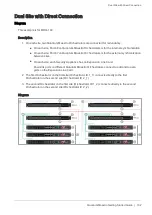
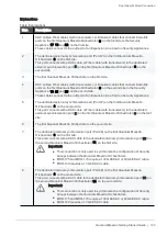
Page 132: ...m Maestro Orchestrators is for the external synchronization between sites n On each site each Security Appliance has an Expansion Line Card Downlink ports on different Quantum Maestro Orchestrators connect to odd and to even ports on the Expansion Line Card 2 The first Orchestrator on the first site Orchestrator ID 1_1 connects directly to the first Orchestrator on the second site Orchestrator ID ...

Page 133: ...rst Quantum Maestro Orchestrator 6 on the second site This port connects with a DAC cable or Fiber cable with transceivers to the dedicated external synchronization port 2 on the first Quantum Maestro Orchestrator 3 on the first site 6 The first Quantum Maestro Orchestrator on the second site 7 The dedicated internal synchronization port Port 48 on the first Quantum Maestro Orchestrator 3 on the f...

Page 134: ...te This port connects with a DAC cable or Fiber cable with transceivers to the dedicated external synchronization port 10 on the second Quantum Maestro Orchestrator 11 on the first site 14 The second Quantum Maestro Orchestrator on the second site 15 The dedicated internal synchronization port Port 48 on the second Quantum Maestro Orchestrator 3 on the first site This port connects with a DAC cabl...

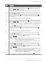
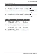
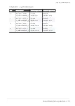
Page 135: ...urity Appliance 3 on the first site member of the Security Group 20 23 Security Appliance 3 on the second site member of the Security Group 20 Table Explanations continued Configuration of the synchronization ports Site Orchestrator Internal Sync Port External Sync Port 1 Orchestrator ID 1_1 denoted as MHO 1_1 Port 48 IP 192 0 2 1 Port 47 IP 203 0 113 1 1 Orchestrator ID 1_2 denoted as MHO 1_2 Por...

Page 136: ...ns n Mounting the Quantum Maestro Orchestrator MHO 175 in a Rack on page 53 n Mounting the Quantum Maestro Orchestrator MHO 140 and MHO 170 in a Rack on page 68 2 On each site connect the cables between n The dedicated internal synchronization ports on the Quantum Maestro Orchestrators n The Security Appliances and the Downlink ports on the Quantum Maestro Orchestrators n The production traffic ne...

Page 137: ...Orchestrator on the second site Orchestrator ID 2_1 Connect ports with the same numbers 2 The second Orchestrator on the first site Orchestrator ID 1_2 The second Orchestrator on the second site Orchestrator ID 2_2 Connect ports with the same numbers Best Practice l On MHO 175 and MHO 170 use Ports 31 on the Quantum Maestro Orchestrators on each site l On MHO 140 use Ports 47 on the Quantum Maestr...

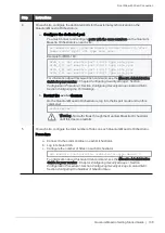
Page 138: ...for your version Chapter Configuring Security Groups Section Configuration Procedure Section Configuring Security Groups in Gaia Clish Section Configuring the Port Settings b Restart the orchd daemon On the Quantum Maestro Orchestrators log in to the Expert mode and run this command orchd restart Warning No traffic flows through the Quantum Maestro Orchestrator until this daemon restarts 5 On each...

Page 139: ...l this daemon restarts Configuring the Site ID on the second site a Connect to the command line on each Orchestrator b Log in to Gaia Clish c Configure the same Site ID 2 on each Orchestrator set maestro configuration orchestrator site id 2 d Restart the orchd daemon on each Orchestrator Log in to the Expert mode and run this command orchd restart Warning No traffic flows through the Quantum Maest...

Page 140: ...ly clone the software and the configuration from the SMO Security Appliance on Site 1 n To create a new Security Group when the SMO Image Cloning is disabled follow the procedure below Procedure a Create a new Security Group that contains interfaces and Security Appliances only from Site 1 b Connect to the command line of the Security Group over SSH at IP Address of Security Group When you log in ...

Page 141: ...transceivers or DAC cables between the dedicated external synchronization ports on the Quantum Maestro Orchestrator Procedure n You must connect fiber cables between ports with the same numbers on the Quantum Maestro Orchestrators on each site Connect fiber cables between these pairs of Quantum Maestro Orchestrators 1 The first Orchestrator on the first site Orchestrator ID 1_1 The first Orchestra...

Page 142: ... each Orchestrator set maestro configuration orchestrator site id 1 4 Restart the orchd daemon on each Orchestrator Log in to the Expert mode and run this command orchd restart Warning No traffic flows through the Quantum Maestro Orchestrator until this daemon restarts Configuring the Site ID on the second site a Connect to the command line on each Orchestrator b Log in to Gaia Clish c Configure t...

Page 143: ...trators on the new site before you perform this step on the Quantum Maestro Orchestrators on the existing site This is to make sure the current configuration is preserved on the new site Procedure a Connect to the command line on the Quantum Maestro Orchestrator b Log in to Gaia Clish c Configure the dedicated port You must connect and configure ports with the same numbers on the Quantum Maestro O...

Page 144: ...e same numbers on the Quantum Maestro Orchestrators on each site set maestro port Quantum Maestro Orchestrator ID Port Label Port Split ID type site_sync Example for MHO 140 Orch_1_1 set maestro port 1 47 1 type site_sync Orch_1_2 set maestro port 1 47 1 type site_sync d Log in to the Expert mode e Restart the orchd daemon orchd restart Warning No traffic flows through the Quantum Maestro Orchestr...

Page 145: ...d In the bottom left corner click Apply In Gaia Clish For information see the Maestro Administration Guide for your version Chapter Configuring Security Groups Section Configuration Procedure Section Configuring Security Groups in Gaia Clish a Connect to the command line on the Quantum Maestro Orchestrator b Log in to Gaia Clish c Apply the configuration set maestro security group apply new config...

Page 146: ...nk ports on different Quantum Maestro Orchestrators connect to odd and to even ports on the Expansion Line Card 2 Port 47 on the first Orchestrator on the first site Orchestrator ID 1_1 connects to the Layer 2 Switch to Port 1 on the first site 3 Port 47 on the second Orchestrator on the first site Orchestrator ID 1_2 connects to the same Layer 2 Switch to Port 2 on the first site 4 Port 47 on the...

Page 147: ...21 on the second Quantum Maestro Orchestrator 22 on the second site 9 DAC cables Fiber cables with transceivers or Breakout cables that connect Downlink ports on the first Quantum Maestro Orchestrator 11 on the first site to the Security Appliance 25 27 and 30 on the first site These cables connect to the odd port of an Expansion Line Card on Security Appliances 10 The dedicated external synchroni...

Page 148: ... 140 requires a 10 GbE DAC cable 17 DAC cables Fiber cables with transceivers or Breakout cables that connect Downlink ports on the second Quantum Maestro Orchestrator 19 on the first site to the Security Appliance 25 27 and 30 on the first site These cables connect to the even port of an Expansion Line Card on Security Appliances 18 The dedicated external synchronization port Port 47 on the secon...

Page 149: ...with a DAC cable to the dedicated internal synchronization port 16 on the first Quantum Maestro Orchestrator 14 on the first site Important n This connection is only used to synchronize the configuration of Security Groups between the Quantum Maestro Orchestrators n MHO 175 and MHO 170 require a 100 GbE DAC or 40 GbE DAC cable n MHO 140 requires a 10 GbE DAC cable 25 Security Appliance 1 on the fi...

Page 150: ...nal Sync Port 1 Orchestrator ID 1_1 denoted as MHO 1_1 Port 48 IP 192 0 2 1 Port 47 IP 203 0 113 1 1 Orchestrator ID 1_2 denoted as MHO 1_2 Port 48 IP 192 0 2 2 Port 47 IP 203 0 113 2 2 Orchestrator ID 2_1 denoted as MHO 2_1 Port 48 IP 192 0 2 15 Port 47 IP 203 0 113 15 2 Orchestrator ID 2_2 denoted as MHO 2_2 Port 48 IP 192 0 2 16 Port 47 IP 203 0 113 16 ...

Page 151: ...W 1 and SW 2 32 VLAN Trunk that accepts these VLAN IDs n 3600 used for a site internal synchronization n 3601 used for a site internal synchronization n 3951 used for external synchronization n 3952 used for external synchronization Important n It is not possible to change the VLAN ID 3951 and the VLAN ID 3952 n The default Site Sync VLAN IDs are l 3600 on Orchestrator ID 1_1 and Orchestrator ID 2...

Page 152: ...nnecting Two Quantum Maestro Orchestrators for Redundancy on page 87 n Connecting Cables to MHO 175 on page 98 n Connecting Cables to MHO 170 on page 109 n Connecting Cables to MHO 140 on page 121 3 On each site connect fiber cables with transceivers or DAC cables between the dedicated external synchronization ports on the Quantum Maestro Orchestrator and the ports on the Layer 2 switch Best Pract...

Page 153: ... your version Chapter Configuring Security Groups Section Configuration Procedure Section Configuring Security Groups in Gaia Clish Section Configuring the Port Settings b Restart the orchd daemon On the Quantum Maestro Orchestrators log in to the Expert mode and run this command orchd restart Warning No traffic flows through the Quantum Maestro Orchestrator until this daemon restarts 5 On each si...

Page 154: ...ure Section Configuring Security Groups in Gaia Clish Section Configuring the Site ID in Dual Site Deployment d Restart the orchd daemon on each Orchestrator Log in to the Expert mode and run this command orchd restart Warning No traffic flows through the Quantum Maestro Orchestrator until this daemon restarts Configuring the Site ID on the second site a Connect to the command line on each Orchest...

Page 155: ...rs assign the new Site Sync VLAN IDs in this way n Orchestrator ID 1_1 and Orchestrator ID 2_1 use the Site Sync VLAN ID based on this formula Base Site Sync VLAN ID you configured 0 n Orchestrator ID 1_2 and Orchestrator ID 2_2 use the Site Sync VLAN ID based on this formula Base Site Sync VLAN ID you configured 1 Example If you configure the Base Site Sync VLAN ID 4800 on all Quantum Maestro Orc...

Page 156: ...configuration automatically on each site and between the sites n To create a new Security Group when the SMO Image Cloning is enabled follow the procedure below Procedure a Create a new Security Group that contains interfaces and Security Appliances only from Site 1 b Connect to the command line of the Security Group over SSH at IP Address of Security Group When you log in the Gaia gClish opens by...

Page 157: ...and Security Appliances only from Site 1 b Connect to the command line of the Security Group over SSH at IP Address of Security Group When you log in the Gaia gClish opens by default Important This connection goes through the Quantum Maestro Orchestrator s management interface you assigned to this Security Group c Configure the total number of Sites set smo security group site amount 2 d Add to th...

Page 158: ... even ports on the Expansion Line Card 2 Port 47 on the first Orchestrator on the first site Orchestrator ID 1_1 connects to the first Layer 2 Switch to Port 1 on the first site 3 Port 47 on the second Orchestrator on the first site Orchestrator ID 1_2 connects to the second Layer 2 Switch to Port 1 on the first site 4 Port 47 on the first Orchestrator on the second site Orchestrator ID 2_1 connec...

Page 159: ...Dual Site with four Switches Quantum Maestro Getting Started Guide 159 Diagram ...

Page 160: ...on the first site 8 A port on the second Layer 2 switch 11 on the first site that connects to a corresponding port 10 on the second Layer 2 switch 12 on the second site 9 A port on the second Layer 2 switch 12 on the second site that connects to the dedicated external synchronization port 25 on the second Quantum Maestro Orchestrator 26 on the second site 10 A port on the second Layer 2 switch 12 ...

Page 161: ...nal synchronization port Port 48 on the first Quantum Maestro Orchestrator 18 on the second site This port connects with a DAC cable to the dedicated internal synchronization port 28 on the second Quantum Maestro Orchestrator 26 on the second site Important n This connection is only used to synchronize the configuration of Security Groups between the Quantum Maestro Orchestrators n MHO 175 and MHO...

Page 162: ... 10 GbE DAC cable 28 The dedicated internal synchronization port Port 48 on the second Quantum Maestro Orchestrator 26 on the second site This port connects with a DAC cable to the dedicated internal synchronization port 20 on the first Quantum Maestro Orchestrator 18 on the first site Important n This connection is only used to synchronize the configuration of Security Groups between the Quantum ...

Page 163: ... Switch Port Port Configuration 1 and 2 SW 1 1 and 32 VLAN Trunk that accepts these VLAN IDs n 3600 used for a site internal synchronization n 3951 used for external synchronization 1 and 2 SW 2 1 and 32 VLAN Trunk that accepts these VLAN IDs n 3600 used for a site internal synchronization n 3952 used for external synchronization Important n It is not possible to change the VLAN ID 3951 and the VL...

Page 164: ...ic networks and the Uplink ports on the Quantum Maestro Orchestrators Follow n Connecting Two Quantum Maestro Orchestrators for Redundancy on page 87 n Connecting Cables to MHO 175 on page 98 n Connecting Cables to MHO 170 on page 109 n Connecting Cables to MHO 140 on page 121 3 On each site connect fiber cables with transceivers or DAC cables between the dedicated external synchronization ports o...

Page 165: ...r your version Chapter Configuring Security Groups Section Configuration Procedure Section Configuring Security Groups in Gaia Clish Section Configuring the Port Settings b Restart the orchd daemon On the Quantum Maestro Orchestrators log in to the Expert mode and run this command orchd restart Warning No traffic flows through the Quantum Maestro Orchestrator until this daemon restarts 5 On each s...

Page 166: ...dure Section Configuring Security Groups in Gaia Clish Section Configuring the Site ID in Dual Site Deployment d Restart the orchd daemon on each Orchestrator Log in to the Expert mode and run this command orchd restart Warning No traffic flows through the Quantum Maestro Orchestrator until this daemon restarts Configuring the Site ID on the second site a Connect to the command line on each Orches...

Page 167: ...rs assign the new Site Sync VLAN IDs in this way n Orchestrator ID 1_1 and Orchestrator ID 2_1 use the Site Sync VLAN ID based on this formula Base Site Sync VLAN ID you configured 0 n Orchestrator ID 1_2 and Orchestrator ID 2_2 use the Site Sync VLAN ID based on this formula Base Site Sync VLAN ID you configured 1 Example If you configure the Base Site Sync VLAN ID 4800 on all Quantum Maestro Orc...

Page 168: ...configuration automatically on each site and between the sites n To create a new Security Group when the SMO Image Cloning is enabled follow the procedure below Procedure a Create a new Security Group that contains interfaces and Security Appliances only from Site 1 b Connect to the command line of the Security Group over SSH at IP Address of Security Group When you log in the Gaia gClish opens by...

Page 169: ... and Security Appliances only from Site 1 b Connect to the command line of the Security Group over SSH at IP Address of Security Group When you log in the Gaia gClish opens by default Important This connection goes through the Quantum Maestro Orchestrator s management interface you assigned to this Security Group c Configure the total number of Sites set smo security group site amount 2 d Add to t...

Page 170: ...mes to the ports on the Quantum Maestro Orchestrator s front panel the default configuration Important The Gaia Operating System on the Quantum Maestro Orchestrator does not let you configure the network settings for the Uplink or Downlink ports You configure all the applicable network settings for the Uplink ports in the Gaia Operating System of the applicable Security Group for example IP addres...

Page 171: ... 18 1 3 eth1 09 Port 1 3 1 19 dl73 Port 1 19 1 4 eth1 13 Port 1 4 1 20 dl77 Port 1 20 1 5 eth1 17 Port 1 5 1 21 dl81 Port 1 21 1 6 eth1 21 Port 1 6 1 22 dl85 Port 1 22 1 7 eth1 25 Port 1 7 1 23 dl89 Port 1 23 1 8 eth1 29 Port 1 8 1 24 dl93 Port 1 24 1 9 eth1 33 Port 1 9 1 25 dl97 Port 1 25 1 10 eth1 37 Port 1 10 1 26 dl113 Port 1 26 1 11 eth1 41 Port 1 11 1 27 dl117 Port 1 27 1 12 eth1 45 Port 1 1...

Page 172: ... 10 eth2 37 Port 2 10 1 26 dl113 Port 2 26 1 11 eth2 41 Port 2 11 1 27 dl117 Port 2 27 1 12 eth2 45 Port 2 12 1 28 dl121 Port 2 28 1 13 eth2 49 Port 2 13 1 29 dl125 Port 2 29 1 14 eth2 53 Port 2 14 1 30 dl129 Port 2 30 1 15 eth2 57 Port 2 15 1 31 dl133 Port 2 31 1 16 eth2 61 Port 2 16 1 32 eth2 Sync Port 2 32 1 Table Second MHO 175 ports and interfaces Notes n When you connect two Quantum Maestro ...

Page 173: ...rt 1 18 1 3 eth1 05 Port 1 3 1 19 dl37 Port 1 19 1 4 eth1 07 Port 1 4 1 20 dl39 Port 1 20 1 5 eth1 09 Port 1 5 1 21 dl41 Port 1 21 1 6 eth1 11 Port 1 6 1 22 dl43 Port 1 22 1 7 eth1 13 Port 1 7 1 23 dl45 Port 1 23 1 8 eth1 15 Port 1 8 1 24 dl47 Port 1 24 1 9 eth1 17 Port 1 9 1 25 dl49 Port 1 25 1 10 eth1 19 Port 1 10 1 26 dl51 Port 1 26 1 11 eth1 21 Port 1 11 1 27 dl53 Port 1 27 1 12 eth1 23 Port 1...

Page 174: ...10 eth2 19 Port 2 10 1 26 dl51 Port 2 26 1 11 eth2 21 Port 2 11 1 27 dl53 Port 2 27 1 12 eth2 23 Port 2 12 1 28 dl55 Port 2 28 1 13 eth2 25 Port 2 13 1 29 dl57 Port 2 29 1 14 eth2 27 Port 2 14 1 30 dl59 Port 2 30 1 15 eth2 29 Port 2 15 1 31 dl61 Port 2 31 1 16 eth2 31 Port 2 16 1 32 eth2 Sync Port 2 32 1 Table Second MHO 170 ports and interfaces Notes n When you connect two Quantum Maestro Orchest...

Page 175: ...3 1 6 eth1 06 Port 1 6 1 34 dl34 Port 1 34 1 7 eth1 07 Port 1 7 1 35 dl35 Port 1 35 1 8 eth1 08 Port 1 8 1 36 dl36 Port 1 36 1 9 eth1 09 Port 1 9 1 37 dl37 Port 1 37 1 10 eth1 10 Port 1 10 1 38 dl38 Port 1 38 1 11 eth1 11 Port 1 11 1 39 dl39 Port 1 39 1 12 eth1 12 Port 1 12 1 40 dl40 Port 1 40 1 13 eth1 13 Port 1 13 1 41 dl41 Port 1 41 1 14 eth1 14 Port 1 14 1 42 dl42 Port 1 42 1 15 eth1 15 Port 1...

Page 176: ...er on the Front Panel Interface Name in Gaia OS Port Name in Gaia OS 23 eth1 23 Port 1 23 1 51 eth1 53 Port 1 53 1 24 eth1 24 Port 1 24 1 52 eth1 55 Port 1 52 1 25 eth1 25 Port 1 25 1 53 eth1 57 Port 1 57 1 26 eth1 26 Port 1 26 1 54 eth1 59 Port 1 54 1 27 dl27 Port 1 27 1 55 eth1 61 Port 1 61 1 28 dl28 Port 1 28 1 56 eth1 63 Port 1 63 1 Table First MHO 140 ports and interfaces continued ...

Page 177: ... Port 2 34 1 7 eth2 07 Port 2 7 1 35 dl35 Port 2 35 1 8 eth2 08 Port 2 8 1 36 dl36 Port 2 36 1 9 eth2 09 Port 2 9 1 37 dl37 Port 2 37 1 10 eth2 10 Port 2 10 1 38 dl38 Port 2 38 1 11 eth2 11 Port 2 11 1 39 dl39 Port 2 39 1 12 eth2 12 Port 2 12 1 40 dl40 Port 2 40 1 13 eth2 13 Port 2 13 1 41 dl41 Port 2 41 1 14 eth2 14 Port 2 14 1 42 dl42 Port 2 42 1 15 eth2 15 Port 2 15 1 43 dl43 Port 2 43 1 16 eth...

Page 178: ...ort 2 27 1 55 eth2 61 Port 2 61 1 28 dl28 Port 2 28 1 56 eth2 63 Port 2 63 1 Table Second MHO 140 ports and interfaces continued Notes n When you connect two Quantum Maestro Orchestrators MHO 140 for redundancy Gaia OS shows l eth1 XX and Port 1 X X for the first Quantum Maestro Orchestrator l eth2 XX and Port 2 X X for the second Quantum Maestro Orchestrator n The tables above show the default co...

Page 179: ...es rack mount Weight With two PSUs 12 488 kg 27 5 lbs Environmental Temperature Operational 0 to 40 C Non Operational 40 to 70 C Humidity Operational 10 to 85 non condensing Non operational 10 to 90 non condensing Altitude 3050 m Noise level Contact Check Point Support Power Input voltage 100 127 VAC 50 60 Hz 3 5 A 200 240 VAC 50 60 Hz 2 9 A Global Power Consumption 242 W Hardware CPU Intel x86 2 ...

Page 180: ...l Information Quantum Maestro Getting Started Guide 180 Feature Parameter Value Interface Speeds 40 100 GbE for ports 1 32 4x10 GbE for ports 1 32 see MHO 175 Splitting Options on page 83 Throughput 3 2 Tbit sec ...

Page 181: ... condensing Non operational 10 to 90 non condensing Altitude 3050 m Noise level 71 6 dB A Power Input voltage 100 127 VAC 50 60 Hz 3 5 A 200 240 VAC 50 60 Hz 2 9 A Global Power Consumption 150 W Typical power with passive cables ATIS 335 W Max power with optical cables assuming 3 5W for each port Hardware CPU Intel x86 2 40 GHz Quad Core RAM 32 GB DDR3 Storage 120 GB SSD Connector cage 32 x QSFP28...

Page 182: ...n condensing Altitude 3050 m Noise level 70 9 dB A Power Input voltage 100 127 VAC 50 60 Hz 4 5 A 200 240 VAC 50 60 Hz 2 9 A Global Power Consumption 165 W Typical power with passive cables ATIS 265 W Max power with optical cables assuming 3 5W for each QSFP28 port and 1 5W for each SFP28 port Hardware CPU Intel x86 1 40 GHz Dual Core RAM 16 GB DDR3 Storage 120 GB SSD Connector cage 48 x SFP28 8 x...

Page 183: ...tions Critical 120 C When the Quantum Maestro Orchestrator crosses this temperature the firmware automatically shuts down the Quantum Maestro Orchestrator Emergency 130 C In case the firmware fails to shut down the Quantum Maestro Orchestrator upon crossing the Critical threshold the Quantum Maestro Orchestrator automatically shuts down upon crossing the Emergency threshold Note This is the temper...

Page 184: ... Harness Pinout Quantum Maestro Getting Started Guide 184 RJ45 to DB9 Harness Pinout To connect a host PC to the Console RJ45 port on the Quantum Maestro Orchestrator an RS232 harness cable DB9 to RJ45 is supplied ...

Page 185: ... 170 MHO 140 Regulated models SN3700C SN2740 SN2410 Manufacturer s name Mellanox Technology Ltd Manufacturer s address Beit Mellanox Yokneam 20692 Israel The models of the declaration described above have been tested by Mellanox EMC Laboratory and were found to comply with the requirements set out in the Council Directive on the Approximation of the Laws of the Member States relating to Electromag...

Page 186: ...A Information Technology Equipment Radio Disturbance Characteristics VCCI VCCI CISPR 32 201 6 Class A Information Technology Equipment Radio Disturbance Characteristics AS NZS RCM AS NZS CISPR 32 201 5 Class A Information Technology Equipment Radio Disturbance Characteristics Safety CE LVD Global Safety EN 609 50 1 2 006 A2 201 3 IEC 609 50 1 2 005 AMD1 200 9 AMD2 201 3 UL CSA 609 50 1 EN 623 68 1...

Page 187: ...4 2014 Class A ICES 003 Issue 6 Class A Information Technology Equipment Radio Disturbance Characteristics VCCI V 3 2015 04 Class A Information Technology Equipment Radio Disturbance Characteristics AS NZS RCM AS NZS CISPR22 2009 A1 10 Information Technology Equipment Radio Disturbance Characteristics Safety CE LVD Global Safety EN 60950 1 2006 A2 2013 IEC 60950 1 2005 AMD1 2009 AMD2 2013 Informat...

Page 188: ...What is the Next Step Quantum Maestro Getting Started Guide 188 What is the Next Step See the Maestro Administration Guide on the Home Page SK article for your software version ...

Reviews: