


Troubleshooting Guide
3-20
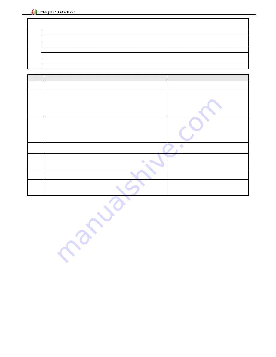
Case
Cause
Action
J1
Caused by printing on cockled paper having a high printing
duty.
Change the paper or duty.
Print with borders.
J2
Paper gets torn off as it drops slantwise under its own weight
during cutting.
Non-recommended grades of paper are liable to this problem
(because of their heavy weighing capacity and slippery reverse
side).
Support the paper when cutting.
Use recommended paper.
J3
With paper on which inks be difficult to dry, such as film-based
paper, blurred print images could result if the paper is cut
immediately after printing. The default setting designed to
prevent this problem is “Ejection Cut” (press the [Online] button
after printing to cut the paper).
Cancel the ejection cut setting of the
main unit and support the paper by hand
during printing.
J4
The driver setting is either [Do Not Cut] or [Print Cut Lines].
Change the driver setting
Page Settings
>
Auto Cut Setting
J5
The main unit has the [Reduce Cutting Dust] mode setting. In
this mode, a yellow line is printed at the cutting position to
prevent cutting dust from being produced on printing.
Turn off [Reduce Cutting Dust] in the
paper preferences on the main unit.
J6
Faulty main controller (cutter driver PCB)
Replace the main controller (cutter driver
PCB)
J7
Cut automatically when printed past the maximum allowable
print length of an application of the OS
Use utilities, such as RIP
12. Cutting failures without error indications
■J1.
Wavy cut surface
■J2.
Residual cutting chips on the reference side
■J3.
Ejection cut setting
■J4.
Normally ended without cutting, or line printed at the cutting position
■J5.
Cut, but with a line printed at the cutting position
■J6.
Cut automatically
Cases
■J7.
Images cut halfway
Summary of Contents for imagePROGRAF IPF9000S
Page 2: ......
Page 3: ......
Page 6: ......
Page 7: ...Chapter 1 Using This Guide...
Page 8: ......
Page 10: ......
Page 11: ...Chapter 2 Trouble Database...
Page 12: ......
Page 72: ......
Page 73: ...Chapter 3 More Sophisticated Fault Isolation Tasks...
Page 74: ......
Page 103: ...Chapter 4 More Sophisticated Fault Isolation Tasks 3 29 Explanatory drawing 7...
Page 118: ......
Page 119: ...Chapter 4 Fault Isolation Tool Collection...
Page 120: ......
Page 153: ...Chapter 5 Miscellaneous Information...
Page 154: ......
Page 175: ...Chapter 6 Main Unit Configuration Diagrams...
Page 176: ......


