


Troubleshooting Guide
5-20
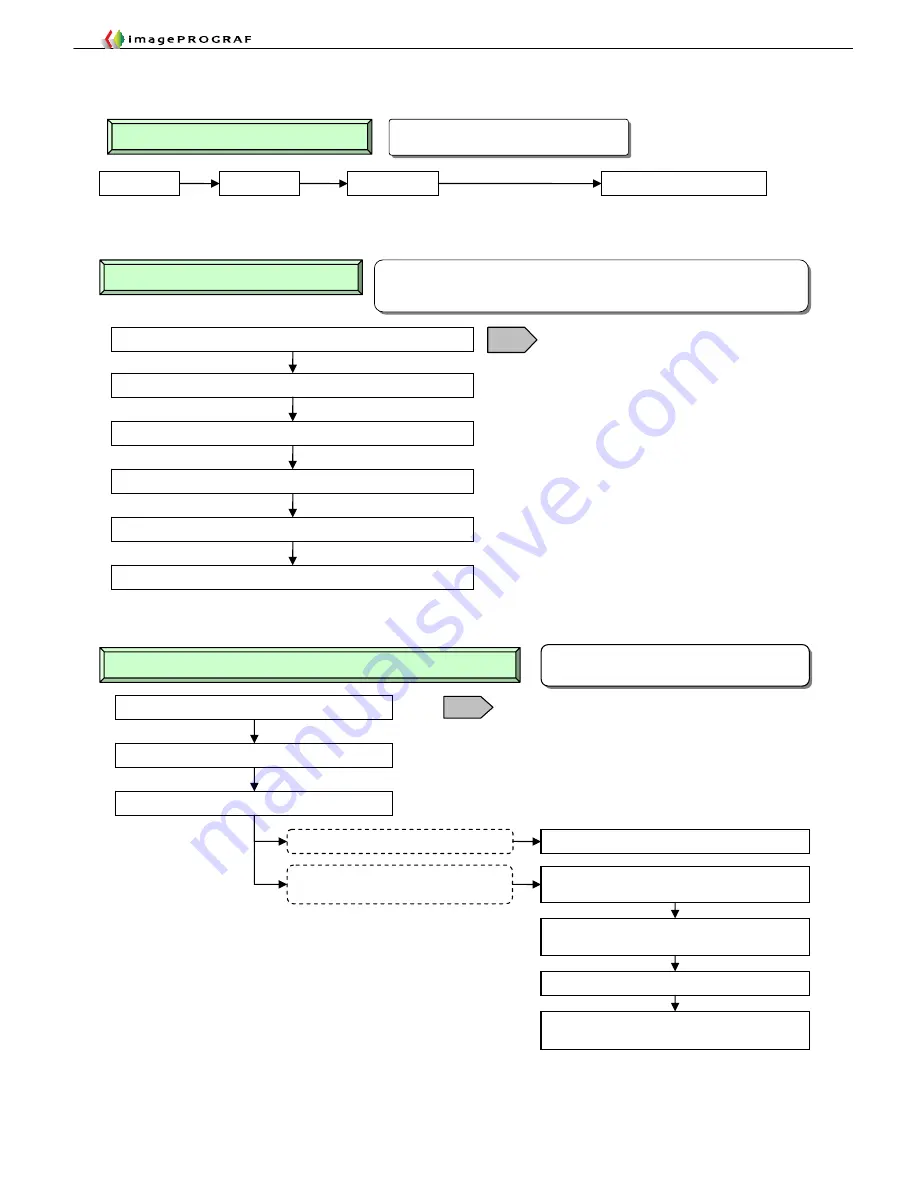
6. Replacing the Head
Unlock the carriage and disconnect the AC cable
Take out the head
Replace the carriage unit
Remount the original head and restart the printer
If the printer has been drained of ink on
carriage unit replacement
Unless the printer has been drained of ink
Advantage:
Low ink consumption
(unless the printer has been drained of ink)
Restart the printer in user mode without a head
mounted (hereafter follow steps similar to
②
)
③
Removing and reinserting a head on carriage unit replacement
Restart the printer in service mode and check the
nozzle check pattern
Initial filling and automatic head adjustment
Mount a new head according to operation panel
guidance
T14
Unlock the carriage and disconnect the AC cable
Take out the head and close the head cover and the top cover
Restart the printer in user mode without a head mounted
Restart the printer in service mode and check the nozzle check pattern
Initial filling and automatic head adjustment
T14
Advantage:
Assures head reusability (allowing faults in the heads to be analyzed)
Disadvantage: Increased ink and MT cartridge consumption (about three times
larger than normal)
Mount a new head according to operation panel guidance
②
Head replacement by servicepersons
Perform automatic head adjustment with the finest grade of
paper available at the customer’s site.
Ink filling will not occur if you mount a new head now.
Advantage:
Low ink consumption
Disadvantage: Unpredictable head reusability
①
Replacing heads from the Main Menu
Main Menu
Maintenance
Replace Heads
On a two-head model, choose either L or R.
Automatic Head Adjustment
Try on the finest grade of paper
available at the customer’s site.
Summary of Contents for imagePROGRAF IPF9000S
Page 2: ......
Page 3: ......
Page 6: ......
Page 7: ...Chapter 1 Using This Guide...
Page 8: ......
Page 10: ......
Page 11: ...Chapter 2 Trouble Database...
Page 12: ......
Page 72: ......
Page 73: ...Chapter 3 More Sophisticated Fault Isolation Tasks...
Page 74: ......
Page 103: ...Chapter 4 More Sophisticated Fault Isolation Tasks 3 29 Explanatory drawing 7...
Page 118: ......
Page 119: ...Chapter 4 Fault Isolation Tool Collection...
Page 120: ......
Page 153: ...Chapter 5 Miscellaneous Information...
Page 154: ......
Page 175: ...Chapter 6 Main Unit Configuration Diagrams...
Page 176: ......


