7. Processing the Image (QA Mode Screen)
– 72 –
3
Set the corresponding density.
Touch or to select a setting from
1 to 29
.
The displayed value on the left is the saved value, and the value on the right is the
modified value.
The analysis value obtained by the Automated ROI or the Fixed ROI will be converted to
a density corresponding to the setting.
The following table is the density when the printer’s LUT is linear, the maximum density
is 3.2 D, and the minimum density is 0.2 D.
4
Set the contrast.
Touch or to select a setting from
1 to 29
.
The displayed value on the left is the saved value, and the value on the right is the modified
value.
Higher values result in higher contrast, and lower values result in lower contrast.
Table 7.4.1B: Setting Values – Density
Setting
1
2
3
4
5
6
7
8
9
10
Density
0.3
0.4
0.5
0.6
0.7
0.8
0.9
1.0
1.1
1.2
Setting
11
12
13
14
15
16
17
18
19
20
Density
1.3
1.4
1.5
1.6
1.7
1.8
1.9
2.0
2.1
2.2
Setting
21
22
23
24
25
26
27
28
29
Density
2.3
2.4
2.5
2.6
2.7
2.8
2.9
3.0
3.1
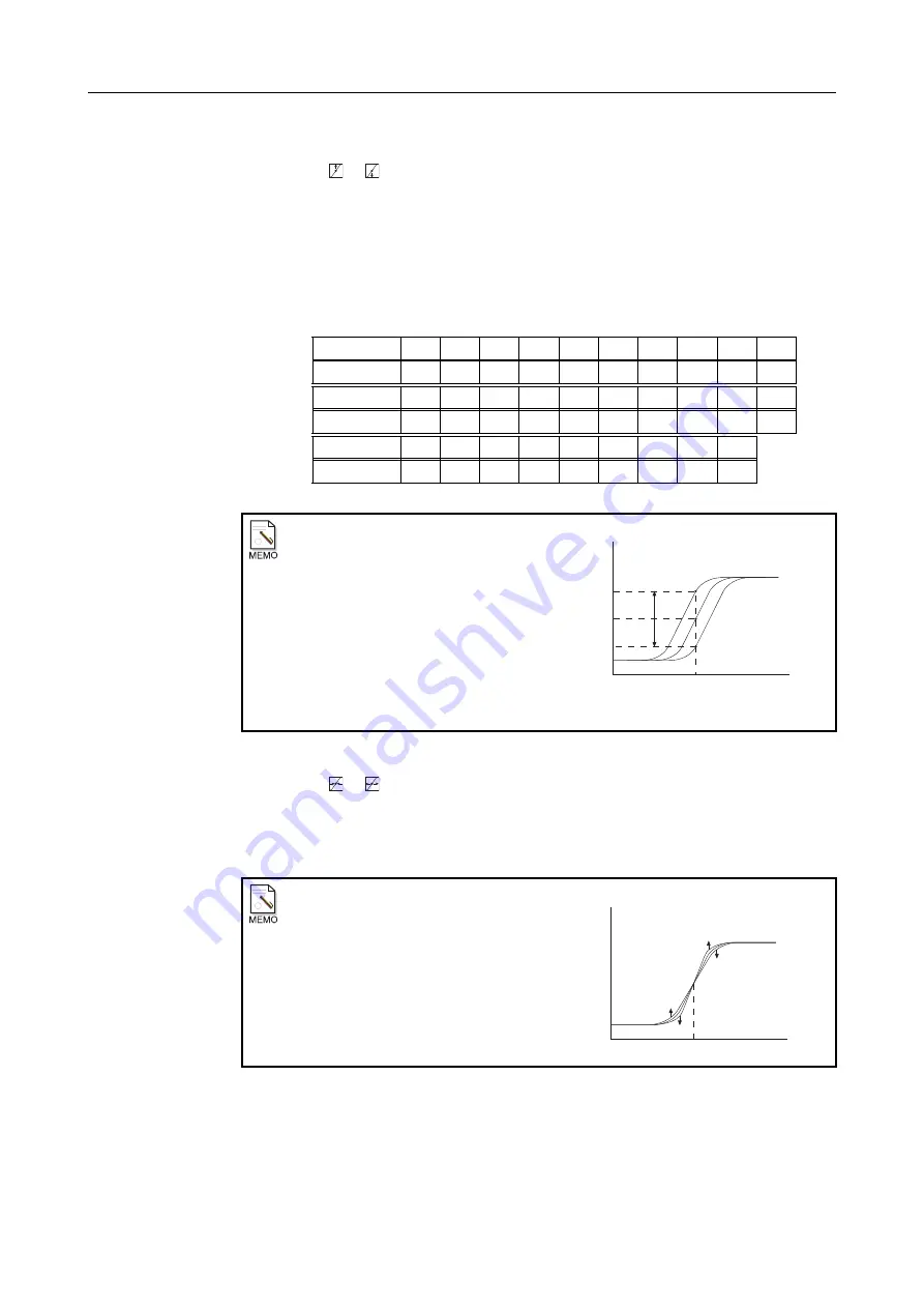
Brightness
By adjusting the brightness, the density
of the whole area can be changed. For
example, a high brightness setting will
shift the LUT graph toward the left,
raising the density of the whole image,
as illustrated in the right.
Similarly, a low brightness setting will
shift the LUT graph to the right,
lowering the density of the whole
image.
Contrast
Adjusting the contrast setting as shown
below changes the contrast of the whole
image.
Density
Pixel
Value
UP
DOWN
Analysis Value
BRIGHTNESS
Density
Pixel
Value
Analysis Value
UP
DOWN
DOWN
UP
Summary of Contents for CXDI-1
Page 9: ...Starting Up Shutting Down 1 Starting Up Shutting Down the CXDI ...
Page 15: ...Exposure and Output 2 Taking an Image 3 Output Control Process Viewer ...
Page 38: ...2 Taking an Image 30 ...
Page 60: ...5 Viewing Multiple Images Multi View Screen 52 ...
Page 70: ...6 Browsing Completed Studies Study List 62 ...
Page 71: ...Processing the Image 7 Processing the Image QA Mode Screen ...
Page 103: ...CXDI Adjustment 8 Calibration 9 Self test ...
Page 110: ...8 Calibration 102 ...
Page 116: ...9 Self test 108 ...
Page 117: ...Troubleshooting 10 Before Calling a Service Engineer 11 Questions and Answers ...
Page 136: ...11 Questions and Answers 128 ...
Page 156: ...B Using the Rejection Reason Input Function 148 ...
Page 162: ...C Using the Sensor Unit Attach Detach Function 154 ...
Page 169: ......


