1 689 989 000
2013-05-02
|
Robert Bosch GmbH
Maintenance | EPS 200 | 45
en
6.2.6
Replacing the intake filter in the test oil tank
!
The intake filter contains oil-based substances and
substances which are a hazard to water. It must be
disposed of in accordance with the applicable regu-
lations.
i
Do not top up the test oil until the intake filter has
been replaced and the EPS 200 has been assembled.
Procedure:
1.
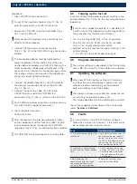
Drain test oil from the test oil tank before replacing
the intake filter (see section 6.2.5, steps 1 to 8).
2.
Unscrew the right housing cover bolts.
3.
Detach the housing cover.
4.
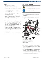
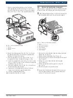
Unscrew the fastening screws (x4) (Fig. 23, Pos. 3)
for the jet chamber unit.
5.
Lift the jet chamber unit (Fig. 23, Pos. 1).
6.
Disconnect the hose (Fig. 23, Pos. 4) from the plug-
in connection (Fig. 23, Pos. 5). To do this, press
down the ring on the screw connection.
7.
Disconnect the two hoses from the quick release
couplings (Fig. 23, Pos. 6).
8.
Disconnect the electrical connecting cable for the
ring light at the plug (Fig. 23, Pos. 7).
9.
Unscrew the ground lead on the jet chamber unit
(Fig. 23, Pos. 2).
10.
Lift the jet chamber unit completely from the
EPS 200.
EPS200
1
BOSCH
458822/52
Ko
1
2
3
4
6
7
3
5
Fig. 23: Removing the jet chamber unit
1 Jet chamber unit
2 Ground wire
3 Fastening screws
4 Hose
5 Plug-in connection
6 Quick-release couplings
7 Ring lamp connector
Procedure for replacing the intake filter:
1.
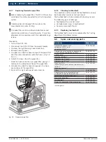
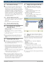
Unscrew the two fastening screws on the tank cover
(Fig. 24, Pos. 1) and lift off the tank cover (Fig. 24,
Pos. 5).
2.
Unscrew the fastening nuts (Fig. 24, Pos. 4) on the
intake filter (Fig. 24, Pos. 3).
3.
Disconnect the intake filter from the intake pipe
(Fig. 24, Pos. 2).
458822/53K
o
1
4
3
2
EPS200
1
BOSCH
5
Fig. 24: Replacing the intake filter
1 Fastening screws
2 Intake pipe
3 Intake filter
4 Nut
5 Tank cover
4.
Slide the new intake filter onto the intake pipe.
5.
Replace the fastening nuts.
6.
Replace the tank cover and screw into place with the
fastening screws.
7.
Reconnect the hoses and the electrical connecting
cable for the ring light to the jet chamber unit.
8.
Screw the ground lead for the jet chamber unit into
place.
9.
Replace the jet chamber unit in the EPS 200 and
secure with the fastening screws.
10.
Replace the side panels and screw into place.
11.
Add test oil (see section 6.2.5, step 8).


