1 689 989 000
2013-05-02
|
Robert Bosch GmbH
34 | EPS 200 | Product description
en
3.5.11 Adapter leads for CRI connection
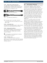
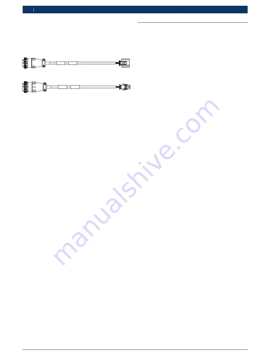
The adapter leads supplied (1 684 465 574 and
1 684 465 575) are required to allow actuation of the
CRI solenoid valve using the EPS 200. These adapter
leads are primarily used for Bosch CRIs.
1 684 465 574
458822-73
Fig. 12: Fig. 12 Adapter lead 1 684 465 574
1 684 465 575
458822-74
Fig. 13: Fig. 13 Adapter lead 1 684 465 575
i
Other adapter leads are available as optional
accessories for the various non-Bosch CRIs and for
Bosch CRINs.
3.5.12 Oil drain hose line
The oil drain hose line supplied (1 680 712 283) is required
to drain the test oil tank (see Maintenance section).
3.5.13 Sealing plug for leak test
The sealing plug supplied is required to perform the
daily leak test. The sealing plug has two threads
(M12 and M14) and is screwed onto the relevant
connection adapter.
!
The sealing plug must be tightened to a torque of
between 25 Nm and 30 Nm.
3.5.14 Protective cover
All tests on a DHK/UI or CRI/CRIN can only be
performed with the cover closed. If the cover is opened
during the test, the test is terminated immediately and
must be re-started.
3.6
Description of function
The EPS 200 is designed as a compact unit. It contains
all components needed for testing a CRI/CRIN
and DHK/UI, e.g. high pressure pump for pressure
generation, test oil tank, flow meter, measuring circuit
board, computer circuit board and LCD display with
touchscreen. To build up the pressure necessary for
testing, a high pressure pump and a high pressure rail
are used. The high pressure pump conveys the test oil,
while the high pressure rail with a pressure control
valve controls the pressure required for testing. The
DHK/UI and CRI/CRIN are connected using a high
pressure connecting line and a connection adapter.
In addition, the CRI/CRIN is actuated by an electric
adapter lead.
The tests on a CRI/CRIN and DHK/UI can only be
performed with the protective cover closed. The
protective cover’s emergency shutdown function aborts
the testing process as soon as the protective cover is
opened and reduces the test oil pressure to < 80 MPa.
The integral two-chamber test oil tank has a capacity of
around seven liters. Coarse impurities are collected in
the first chamber. In the second chamber, the test oil is
brought to the correct testing temperature. The EPS 200
system software can be used to test the most important
functions on the DHK/UI, such as opening pressure
1 and 2, vibration control, combination tightness, seat
tightness and the jet pattern. The illumination in the jet
chamber allows the DHK/UI’s jet pattern to be assessed.
When testing the jet pattern on a DHK/UI, the air flow
controller for the internal extractor (Fig. 1, Pos. 8) is
used to ensure that at little test oil vapor as possible
can escape. A leak test is performed on the CRI/CRIN
and the injection quantity and return quantity can be
measured at full load and when idle.

