1 689 989 000
2013-05-02
|
Robert Bosch GmbH
44 | EPS 200 | Maintenance
en
6.2.5
Replacing the test oil
!
Before replacing the test oil, the EPS 200 must be
turned off and disconnected from the power supply.
!
During use, the test oil is subject to the effects of
evaporation, temperature, pressure, oxidation and
the impact of foreign matter. Regular checking is
therefore essential to ensure compliance with the
necessary test oil quality standard when checking
nozzle-and-holder assemblies and injectors. The
test oil must always be replaced if it is considerably
darker than in the as-new condition. Contaminated
test oil can result in biased measured values and
damage both the EPS 200 and injectors/nozzle-and-
holder assemblies during testing.
Authorized types of test oil:
Oil type
Manufacturer
SHELL Calibration Fluid S 9365
Shell International
SHELL V-OIL 1404
Shell Germany
SHELL Normafluid B. R.
SHELL France
VISCOR
Calibration Fluid 1487 AW-2
Rock Vallery
CASTROL
fluido para Calibracao 4113
Castrol Brazil
ESSO EGL 70 147
Esso AG
BENZ UCF-1 Calibration Fluid
Benz Oil
DIVINOL Calibration Fluid 2928V3
Gmelin GmbH &
Co. KG
Procedure:
1.
Turn off the EPS 200.
2.
Disconnect the EPS 200 from the power supply.
3.
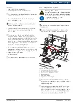
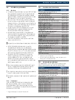
Unscrew the fastening screws (8x) on the left of the
housing cover (Fig. 22, Pos. 6).
4.
Remove housing cover (Fig. 22, Pos. 5).
5.
Unscrew the ground lead on the side panel of the
housing (Fig. 22, Pos. 7).
!
As soon as the quick release coupling is attached
to the EPS 200, test oil flows through the hose
line. Always place the end of the hose line in the oil
collecting tank first.
6.
Place the end of the 1.5 m hose line (Fig. 22, Pos. 4;
1 680 712 283) without the quick release coupling in
the oil collecting tank (Fig. 22, Pos. 3).
7.
Insert the 1.5 m hose line (1 680 712 283) with quick
release coupling into the quick release coupling on
the test oil tank (Fig. 22, Pos. 1).
Test oil flows into the oil collecting tank.
EPS 20
0
1l
BOSCH
458822-4
5
6
2
1
3
7
4
X20
8
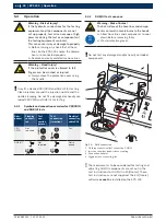
Fig. 22: Draining the test oil
1 Test oil tank quick-release coupling
2 Settling chamber quick-release coupling
3 Oil collector
4 Hose
5 Housing cover
6 Fastening screws
7 Ground wire
8 Oil cooler quick-release coupling
8.
Once the test oil has drained out of the test oil tank,
insert the hose line into the quick release coupling
on the settling chamber (Fig. 22, Pos. 2).
Test oil flows from the settling chamber into the
oil collecting tank.
9.
Once the test oil has drained out of the settling
chamber, insert the hose line into the quick release
coupling on the oil cooler (Fig. 22, Pos. 8).
Test oil flows from the oil cooler into the oil
collecting tank.
10.
Once the test oil has drained out of the oil cooler,
disconnect the hose line from the quick release
coupling.
11.
Use a clean cloth to clean the test oil tank.
12.
Screw the ground lead onto the housing cover.
13.
Replace the housing cover and screw into place.
!
If the test oil is added too quickly, it is possible that it
will run out of the upward facing flushing outlet or the
connection for the external extractor (Fig. 1, Pos. 5).
14.
Pour the new test oil (ISO 4113) into the jet cham-
ber (Fig. 3, Pos. 2) very slowly and carefully. The
test oil tank holds around 6.5 liters.
15.
Add test oil until it reaches the upper marking in
the oil level display (Fig. 1, Pos. 9).
"
Replacement of the test oil is complete.


