


Deploying Avaya IP Office™ Platform IP500 V2
Page 204
15-601042 Issue 30j (18 May 2015)
IP Office™ Platform 9.1
Comments on this document? [email protected]
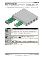
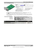
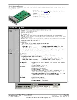
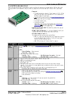
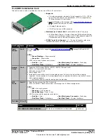
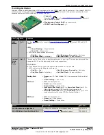
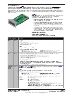
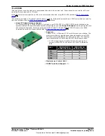
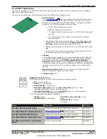
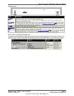
13.2.7 ETR6 Card
This card is used to add 6
ETR
phone extension ports to an IP500 V2 control unit. This card is only supported by
IP500 V2 systems running in IP Office Basic Edition - PARTNER® Mode or IP Office Basic Edition (U-Law) modes.
It also includes 2 analog extension ports which are for emergency use only when the card is fitted with an analog trunk
daughter card. A further 4 RJ45 ports (9 to 12) are provided for trunk connections when an IP500 trunk daughter card is
fitted to this card.
·
Supports
ETR
and analog phones. Each ETR phone can be used for an ETR
or analog phone. Support for ETR 34D phone is limited to a
maximum of 2 per ETR6 card and 4 in total.
·
Paging to external paging equipment is not supported via ETR6
ports. It is supported via POT ports.
·
The only analog phones tested by Avaya for IP500 V2 are the
Avaya 6200 Series. If other analog phones are used, it is the
customer's own responsibility to ensure that those phones work
as required.
·
This card is only supported by IP500 V2 systems running in IP
Office Basic Edition - PARTNER® Mode or IP Office Basic Edition
(U-Law) modes. The card is not supported in other systems or if
the system is changed to A-Law operation.
·
Maximum per Control Unit: 3.
·
IP500 Trunk Card Support:
1.
The IP500 BRI trunk daughter card is not supported.
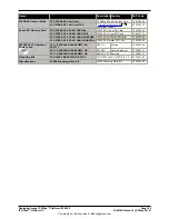
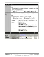
Port Type Ports
Features
ETR
1 to 6
·
REN 1.
·
DTMF dialing only.
·
Message waiting indication 51V stepped.
·
ICLID mode Bellcore 202.
LEDs
·
No status LED are used for ETR ports.
·
LED1 is also used for base card status:
·
Red On = Error
·
Red Slow Flash = Initializing.
·
Red Flash every 5 seconds = Card okay.
·
Red Fast Flash = System shutdown.
EF
7 to 8
·
If fitted with an IP500 Trunk Daughter card, during power failure both these ports are
connected to analog trunk port 12.
·
Supports ICLID modes DTMFA, DTMFC, DTMFD, FSK and UK20.
·
REN 2 (1 for external bell device).
·
Off-Hook current: 25mA
·
Ring Voltage: 40V.
·
Intended for connection to two-wire analog phones, the ports do not include a ringing
capacitor. For connection to 4-wire analog phones, connection should be via a master socket
with ringing capacitors.
·
No status LEDs are used for analog phone extensions.
Optional
Trunk
Ports
9 to 12
Depends on the type of trunk daughter card fitted. The ETR6 can be fitted with either a
Analog
Trunk
card or
PRI Trunk
card.
LEDs
LED use depends on the type of daughter card installed on the base card:
·
LED 9 is also used for daughter card status.
·
Red On = Error
·
Red Slow Flash = Initializing.
·
Red Flash every 5 seconds = Card okay.
·
Red Fast Flash = System shutdown.
Analog
Card
·
Green on = V1: Card installed. V2: Line connected to the port but idle.
·
Green flashing = Line in use.
PRI Card
·
Off = No trunk present.
·
Green on = Trunk present.
·
Green flashing = Trunk in use.
·
Red/Green Fast Flash (port 9) or Green Fast Flash (port 10) = Alarm
indication signal (AIS) from the trunk remote end.
·
Red with Green Blink (port 9) or Green Blink (port 10) = Port in loopback
mode (set through IP Office System Monitor).
39
39
210
213