


Structure and function
72
Cataya Special BAH0109-1 02.21
5.12.1.4 Slide
gate
The seed flows out of the seed hopper through
the hopper opening in the seed housing.
Each coarse and fine metering wheel has a slid-
ing shutter (Fig. 58/1) to adjust the seed hopper
opening.
Fig. 58
For seeding
with coarse metering wheels, the sliding
shutters for the fine metering wheels are
closed
with fine metering wheels, the sliding shut-
ters for the coarse metering wheels are
closed.
The sliding shutter position
of the active metering wheels can
be found in the "Setting values" table, page 68.
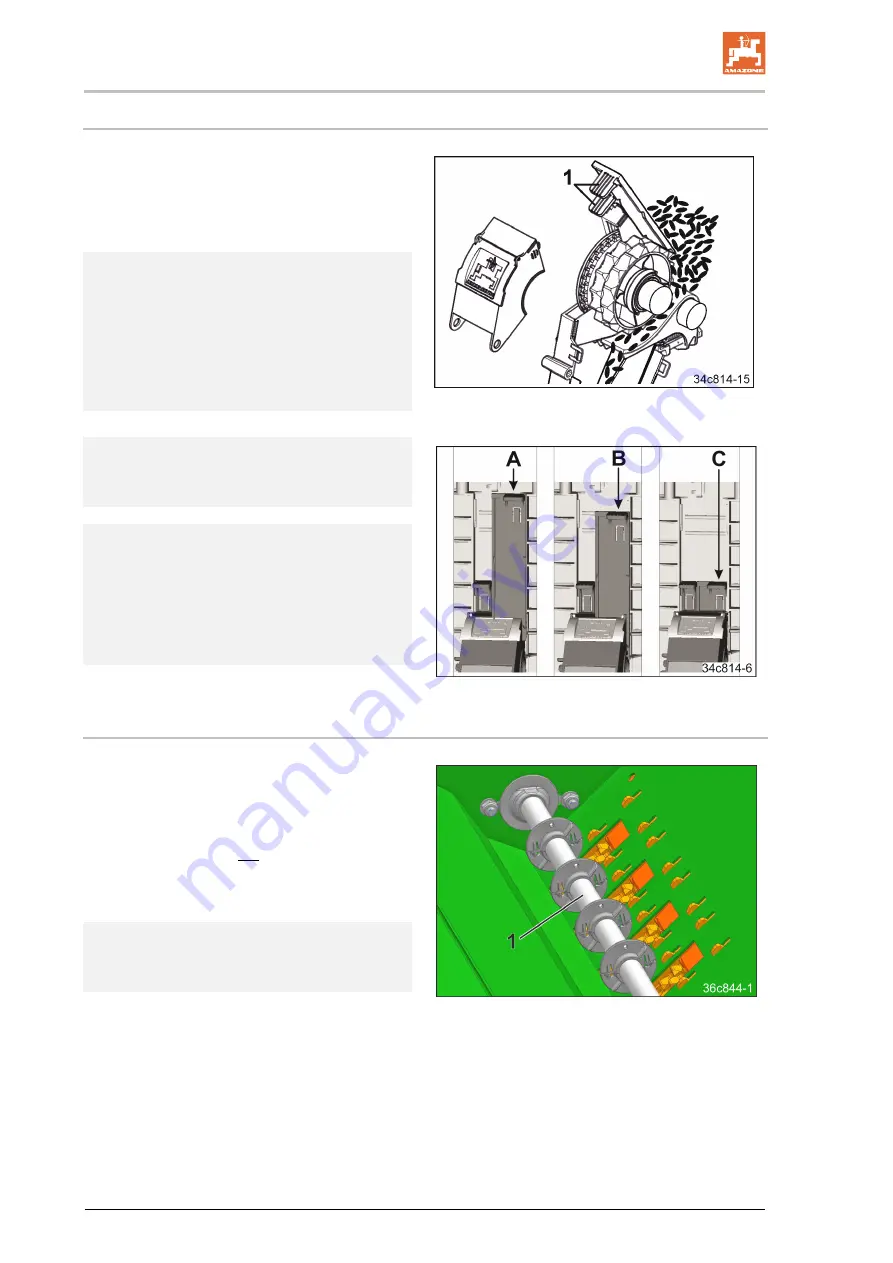
Fig. 59
Each sliding shutter (Fig. 59) can latch into one
of the three positions:
A = Open
B = 3/4 open
C = Closed
5.12.1.5 Agitator shaft support
When seeding spelt-type seed, the stirring ele-
ments on the rotating agitator shaft (Fig. 60/1)
prevent faulty seeding caused by seed blockage
in the seed hopper.
The agitator shaft may not rotate when seeding
certain seed types, e.g. with rapeseed, which
can become sticky due to the intensive stirring
action of the agitator shaft.
Fig. 60
Information on support from the agitator shaft,
depending on the seed type, can be found in
the "Setting values" table, page 68.
Summary of Contents for Cataya 3000 Special
Page 2: ......
Page 99: ...Structure and function Cataya Special BAH0109 1 02 21 99 Fig 107 ...
Page 240: ...Hydraulic diagram 240 Cataya Special BAH0109 1 02 21 Fig 321 ...
Page 241: ......
Page 242: ......


