T E C H N O L O G Y
F O R
T H E
W E L D E R ´ S
W O R L D .
www.binzel-abicor.com
EN
Original operating instructions
iROB
®
501 PRO
Robot welding system with Controller KINETIC wire feed control unit
Page 1: ...T E C H N O L O G Y F O R T H E W E L D E R S W O R L D www binzel abicor com EN Original operating instructions iROB 501 PRO EN Robot welding system with Controller KINETIC wire feed control unit...
Page 2: ...C EN 25 6 3 Shortening the wire guide for the cable assembly EN 25 6 4 Moving the robot into the maintenance position EN 26 6 5 Attaching the Wire Buffer KINETIC to the robot EN 26 6 6 Mounting the Pu...
Page 3: ...N 82 8 Decommissioning EN 83 9 Maintenance and cleaning EN 83 9 1 Maintenance and cleaning intervals EN 84 9 2 Cleaning the device EN 85 9 3 Maintenance work on the wire feed control unit EN 86 9 3 1...
Page 4: ...iROB 501 PRO 13 4 3 Example of setting output data EN 115 13 4 4 Details of I O data EN 116 13 4 5 Functions EN 123 13 4 6 Control timing EN 125 14 Accessories EN 126 15 Spare parts and consumables EN...
Page 5: ...wer source and enables the mX Kinetic welding procedure by balancing the Push Feeder KINETIC and Pull Feeder KINETIC modules The Pull Feeder KINETIC and Push Feeder KINETIC modules are used for the au...
Page 6: ...eplate 1 3 Signs and symbols used The following signs and symbols are used in the operating instructions Fig 3 Push Feeder KINETIC nameplate Fig 4 Pull Feeder KINETIC nameplate Fig 5 Wire Buffer KINET...
Page 7: ...is wet 2 2 Responsibilities of the user Ensure that only suitably qualified personnel perform work on the device or system Suitably qualified personnel are those who are familiar with the basic regula...
Page 8: ...rsonal protective equipment Personal protective equipment consists of protective clothing eye protection protective gloves and safety shoes Read and observe the operating instructions Wear eye protect...
Page 9: ...for using the iROB POWER App control app 1 driving carriage 1 base 1 operating instructions for the iCOOL 1200 Cooling unit Order the equipment parts and wear parts separately The order data and ID nu...
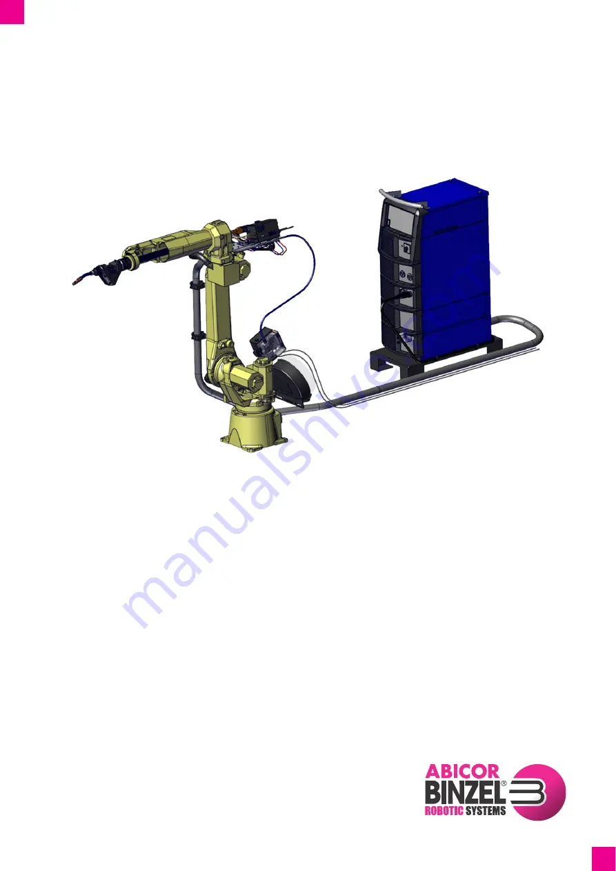
Page 10: ...n Fig 6 iROB 501 PRO structure example A Pull Feeder KINETIC with cable assembly and iCAT mini robot mount B Wire Buffer KINETIC C Wire feed control unit KINETIC system D iROB 501 welding power source...
Page 11: ...connection E Power supply connection welding torch side F Wire feed control unit G Cooling unit optional H Driving carriage optional I Workpiece connection J Not assigned K Mains control LED mX Standa...
Page 12: ...Arc dynamics button R Release start welding end crater parameter button S Penetration control button T Move frequency button U Cooling unit on off button optional V Synergy mode ON OFF button W Weld...
Page 13: ...shielding gas post flow time During welding the set value can be displayed on the digital display G Function button Selects internal functions If the button is pressed for 1 second or longer the LED...
Page 14: ...an impermissible combination is selected the LED flashes M Welding wire material selection button Selects the desired welding wire material The selection option depends on the installed options The LE...
Page 15: ...x cored wire is selected LED on penetration control switched on LED off penetration control switched off T Move frequency button Defines the double pulse frequency if mX Move DC welding procedure is s...
Page 16: ...rs or if the device overheats 10 Faults and troubleshooting on page EN 93 AB USB port Data can be read from or stored to a USB storage device via the port AC Input for service The interface is used ex...
Page 17: ...TIC The Push Feeder KINETIC is part of the wire feeder system The Push Feeder KINETIC has a 2 roll drive and is solely used for wire feeding The 2 roll drive feeds the welding wire at a constant wire...
Page 18: ...INETIC is part of the wire feeder system The Pull Feeder KINETIC s torch interface is compatible with welding torches in the ABIROB W series Fig 12 Pull Feeder KINETIC structure A Welding torch cable...
Page 19: ...evice is equipped with an optional Wi Fi router all device functions can also be controlled and programmed via the optional iROB POWER App control app 14 Accessories on page EN 126 Fig 13 Wire Buffer...
Page 20: ...requency 50 60 Hz Max current consumption 36 A Max power consumption 25 kVA 22 9 kW Fuse on mains side 32 A slow blow Zmax mains supply 0 038 Adjustable range 30 A to 500 A Working voltage 12 V to 45...
Page 21: ...ration Ambient temperature 0 C to 40 C Relative humidity 20 to 80 non condensing Tab 7 General data for the wire feed control unit Number of controlled axes 2 Drive system AC servo motor Position feed...
Page 22: ...y cycle 100 Air pressure 1 5 MPa Weight 1 2 kg Robot Internal and external cable feed Water cooling system Separate cooling unit Tab 10 General data for Wire Buffer KINETIC Welding process CO2 MAG MIG...
Page 23: ...loyees are working Place the device on a suitable base flat solid dry on which it will not topple over Note the weight of the device when lifting it 4 5 Technical data for the welding power source on...
Page 24: ...ARNING Electric shock due to defective cables The use of damaged or improperly installed cables may result in a potentially fatal electric shock Check all live cables and connections for proper instal...
Page 25: ...nclosed wire guide assembly instructions in relation to handling the wire guide 1 Insert the wire guide until it reaches the stop in the cable assembly 2 Determine excess length a B 3 Shorten the wire...
Page 26: ...instruction is for example purposes and can differ depending on the robot type 1 Use the cylinder head screws to attach the mounting plate D to the shoulder part of the robot A 2 Use the wing screws...
Page 27: ...ch the robot mount A to the intermediate flange C 4 Insert the coaxial cable D into the Pull Feeder KINETIC B cable assembly connector 5 Use the cylinder head screw C to secure the coaxial cable D Fig...
Page 28: ...ting the Pull Feeder KINETIC cable assembly All cables in the cable assemblies are labeled Disconnect the device from the power supply Connecting the welding power cable 1 Use the cylinder head screws...
Page 29: ...b from the intermediate cable assembly 3 Connect the encoder cable X6b from the cable assembly Pull Feeder KINETIC to the encoder cable X6b from the intermediate cable assembly 4 Guide the motor and e...
Page 30: ...socket X7b 2 Insert the cable X1b in the connector X1b 3 Insert the control lead X2b in the connector X2b 4 Connect the shielding gas line 5 Connect the compressed air hose Fig 26 Connectors on the bu...
Page 31: ...5 Connect the welding torch control lead X2a to the connector B on the welding power source 6 10 Connecting the wire conduit 1 Attach the wire conduit to the Push Feeder KINETIC s guide adapter Fig 11...
Page 32: ...e intermediate cable assembly to the robot taking care to ensure that no strain is exerted on it when the robot moves 6 12 1 Attaching the neckliner 1 Open the front cover D 2 Loosen the pressure leve...
Page 33: ...B to connect the torch neck A to the interface C After a longer period of use it may no longer be possible to loosen the torch by hand A special hook wrench is available as an accessory for this purp...
Page 34: ...he metal components indicated on the figure Fig 31 Fig 31 Live components NOTICE Material damage due to exceeding the maximum duty cycle If the device is operated for longer than the maximum duty cycl...
Page 35: ...ons 6 Feed the welding wire by pressing the wire feed in trigger C The actual setting depends on the welding conditions and the welding wire used 7 Turn the pressure lever A and set the contact pressu...
Page 36: ...over 2 Pull out the pressure lever D thereby lifting the pressure roll C off the conveyor roller A 3 Insert the welding wire through the through feed guide E into the welding torch WARNING Electric sh...
Page 37: ...ry due to rotating feed roller Body parts hair or clothing can be drawn in when the wire feeder s feed roller rotates This may result in serious injuries Do not reach into the feed roller Do not wear...
Page 38: ...h to 0 2 Press and hold the Function and Enter buttons simultaneously and set the main switch back to I Keep both buttons pressed until PAS Loc are displayed alternately in the left digital display 3...
Page 39: ...t least 3 seconds PAS Loc flashes alternately in the left digital display 2 Set the hundreds digit with the Parameter setting knob 3 Press the Parameter selection button The tens digit starts to flash...
Page 40: ...the welding current voltage immediately after welding starts Main welding parameter Defines the welding current voltage during welding End crater filling parameter Defines the welding current voltage...
Page 41: ...8 1 0 1 2 0 8 1 0 1 2 Standard 97 5 Ar 2 5 CO2 CrNi 0 8 1 0 1 2 0 8 1 0 1 2 Standard CrNi Ferr 0 8 1 0 1 2 0 8 1 0 1 2 Standard mX Pulse DC 82 Ar 18 CO2 Fe 0 8 1 0 1 2 1 6 0 8 1 0 1 2 High standard Po...
Page 42: ...inetic AlMg4 5 1 0 1 2 1 6 mX Kinetic AlSi5 12 1 2 1 6 mX Kinetic mX Kinetic Pulse 82 Ar 18 CO2 Fe 0 8 1 0 1 2 mX Kinetic Fe galvanized 0 8 1 0 1 2 mX Kinetic 92 Ar 8 CO2 Fe 0 8 1 0 1 2 mX Kinetic 97...
Page 43: ...ing parameters welding current and welding voltage 7 Set the end crater filling parameter 8 Set the shielding gas post flow time 9 Save the parameters 7 4 1 Setting the welding procedure 4 1 1 Control...
Page 44: ...parameter F LED shielding gas post flow Tab 16 Welding sequences Sequence Description Shielding gas pre flow A This sequence allows shielding gas to flow out before the arc ignites Start welding param...
Page 45: ...1 Press the Parameter selection button repeatedly until the Main welding parameter Start welding parameter or End crater filling parameter LED illuminates 2 Verify that LED A amperes is illuminated 3...
Page 46: ...rection is executed based on the value automatically assigned to the welding current In synergy mode OFF the voltage can be set separate from the welding current V A m min IE I6 V 1 Press the Synergy...
Page 47: ...e touches the component and spatter occurs The seam is too narrow The welding voltage is too low The seam is too wide The penetration is too deep The welding current is too high The seam is too narrow...
Page 48: ...to 20 6 0 5 0 to 6 0 1 2 280 to 300 29 to 32 40 to 50 15 to 20 9 0 6 0 to 8 0 1 2 300 to 350 32 to 34 40 to 45 15 to 20 12 0 10 0 to 12 0 1 2 320 to 350 33 to 36 25 to 35 20 to 25 Tab 20 Example of w...
Page 49: ...1 2 300 to 350 32 to 35 30 to 35 20 to 25 Front 300 to 350 32 to 35 30 to 35 20 to 25 Back 1 6 380 to 420 36 to 39 35 to 40 20 to 25 Front 380 to 420 36 to 39 35 to 40 20 to 25 Back 19 5 to 7 400 to...
Page 50: ...0 31 80 1 6 380 34 80 7 1 2 280 30 40 1 4 350 32 50 1 6 380 34 65 8 1 2 300 31 30 1 4 350 33 45 1 6 380 34 52 9 1 2 320 32 30 1 4 350 34 40 1 6 380 34 40 Tab 24 Material steel shielding gas mixed gas...
Page 51: ...0 29 to 30 35 12 0 10 0 1 180 to 200 25 to 27 45 2 180 to 200 25 to 28 45 3 180 to 200 25 to 28 45 16 0 12 0 1 220 to 230 25 to 28 45 2 220 to 230 25 to 28 45 3 210 to 230 25 to 28 45 Focus here Appro...
Page 52: ...ers Welding current A Arc voltage V Welding speed cm min 6 0 1 170 25 to 26 30 2 180 26 to 27 30 9 0 1 270 29 to 30 30 2 290 30 to 31 30 12 0 1 280 30 to 31 40 2 330 33 to 34 40 19 0 Front 1 300 31 to...
Page 53: ...parameters for single pass welding high speed mode Sheet thickness t mm Seam type Number of layers Welding current A Arc voltage V Welding speed cm min 3 2 1 140 24 to 25 50 6 0 1 130 23 to 24 25 2 15...
Page 54: ...0 20 to 21 Slight oscillation 2 280 26 to 27 Slight oscillation 3 280 26 to 27 Slight oscillation 4 280 26 to 27 Slight oscillation 5 280 26 to 27 Slight oscillation 6 280 26 to 27 Oscillation 7 280 2...
Page 55: ...32 Example of welding parameters with horizontal fillet welds Sheetthickness t mm Wire diameter mm Welding current A Arc voltage V Welding speed cm min Free wire end mm Gas flow l min 1 5 1 2 60 to 8...
Page 56: ...frequency function is only available in the mX Move DC welding procedure 7 7 4 Setting kinetic move Kinetic move welding alternates between mX Kinetic welding and pulse welding It can increase the he...
Page 57: ...tal display 4 Set a frequency value between 0 1 Hz and 30 Hz with the Parameter setting knob 5 Press the Parameter selection button The pulse welding ratio in a switchover frequency cycle appears on t...
Page 58: ...eactivating the button tones ON OFF ON F23 setting the time period until stand by mode 0 to 10 min 0 min F24 setting the wire feed speed ON OFF OFF F25 F28 setting external outputs 0 4 0 F29 F32 setti...
Page 59: ...er source ID 1 to 999 1 F82 starting pulse time configuration for aluminum 0 to 2 s 0 3 s F83 setting the number of pulses during the start process for aluminum 10 to 300 100 F84 starting the pulse fe...
Page 60: ...feed problems can occur The wire feed rolls do not run evenly This can be detected by monitoring the wire feed motor current The warning level is factory set to 70 of the normal continual motor curren...
Page 61: ...burn time backburn voltage By setting the backburn time F17 and backburn voltage F18 optimally it is possible to prevent the welding wire from adhering to the component at the end of the welding proce...
Page 62: ...ivating the maximum capacity of the cooling fan The speed of the fan motor and thus the cooling capacity is controlled depending on the temperature measured in the power source This Eco mode saves ene...
Page 63: ...e to check which welding current value was automatically set The nominal wire feed speed is between 0 6 m min and 22 m min These values may differ depending on the welding process OFF function The wir...
Page 64: ...efore the arc is called necking and is shown below Detecting this necking and quickly reducing the welding current at the correct moment prevents molten material from being flung out by the force of t...
Page 65: ...til the desired result is achieved F38 switching on advanced welding circuit resistance measurement The arc voltage can be determined via the corresponding welding power source terminal Use the option...
Page 66: ...seconds Adjustable range ON OFF Default value OFF Storage option Yes Description F45 sets the start and end crater filling parameters for a set period of time OFF inactive ON parameters from F46 and F...
Page 67: ...be saved Can be saved 7 Can be saved Can be saved 8 Can be saved Can be saved Can be saved Adjustable range 0 to 8 Default value 0 Storage option No Description Defines which data is written to the D...
Page 68: ...k time must be increased If the welding wire tip becomes too sharp and a very strong arc occurs the pulse peak time must be shortened To make further improvements the pulse peak current must be adjust...
Page 69: ...ut before it hardens F67 setting the selection of current values start welding parameter end crater parameter When the end crater filler function is switched on the current value for the start paramet...
Page 70: ...heat input at the start of the arc F84 starting the pulse feed setting for aluminum Used for mX Kinetic welding with aluminum wire Increasing the value shortens the arc length Decreasing the value inc...
Page 71: ...result 1 Sb1 3 Adjustment result 2 Sb2 4 Adjustment result 3 Sb3 5 Adjustment result 4 Sb4 6 Lead time If adjustment problems arise contact the service department and have the aforementioned adjustmen...
Page 72: ...width from narrowing at the start position but the welding wire protrudes excessively reducing the suppression of spatter generation F90 setting the backburn retraction quantity Adjust the protruding...
Page 73: ...no memory location number is displayed blinking in the right digital display and the JOB No LED is illuminated 2 Select the desired memory location number job no using the Parameter setting knob If a...
Page 74: ...ress and hold both buttons until dEL is displayed in the left digital display 4 Release the buttons As long as dEL is displayed in the left digital display the welding power source is in delete mode T...
Page 75: ...lculated by the device s software and cannot be used as a control value for the measuring instrument 7 10 2 Adjusting parameters during the welding process The welding current and welding voltage can...
Page 76: ...unction and Shielding gas check buttons simultaneously and set the main switch to I 3 Press the buttons until End appears in both digital displays Initialization starts 4 When End is displayed in both...
Page 77: ...time 0 1 s AC pre_feed Starting wire feed speed 0 1 m min D pre_iset Starting current 1 A AD wld_feed Wire feed speed 0 1 m min E pre_vset Starting voltage 0 1 V AE cre_feed End crater wire feed spee...
Page 78: ..._ratio Welding EN ratio 1 AR CrilsetStep2 Double click adjustment value 1 A S pls_pki_adj Pulse peak current Fine adjustment 1 A AS WModeTblNb Welding table no 1 T pls_pkt_adj Pulse peak time Fine adj...
Page 79: ...ed under the path BINZEL_iROB_WELDING DAT DAT00001 A CSV file is stored for every welding process If the path BINZEL_iROB_WELDING DAT DAT00001 already exists the folder DAT00002 is stored under BINZEL...
Page 80: ...b until USB appears on the left hand digital display 5 Twist the Parameter setting knob counterclockwise until the desired data backup is displayed 1 welding parameters 2 internal function settings 3...
Page 81: ...4 Twist the Parameter setting knob until USB appears on the left hand digital display 5 Twist the Parameter setting knob counterclockwise until the desired data backup is displayed 1 welding paramete...
Page 82: ...ersion for manufacturer and service department 1 Set the main switch to 0 2 Press and hold the Function button and set the main switch to I The product number is displayed in the left and right digita...
Page 83: ...become damaged or are improperly installed Check all live cables and connections for proper installation and damage Have any damaged deformed or worn parts replaced by a qualified electrician only WAR...
Page 84: ...e feed rolls for dirt and clean if necessary Check the bottom of the device for cleanliness and clean if necessary Pull Feeder KINETIC Check the wire feed rolls for dirt and clean if necessary Check t...
Page 85: ...re Buffer KINETIC Check the wire guide for wear and damage clean and replace worn components No longer than 1 000 operating hours or more frequently depending on the location Clean the device 9 2 Clea...
Page 86: ...screws C 2 3 Pull the conveyor roller B off the pinion A 4 Insert a new conveyor roller with a suitable groove for the required wire diameter so that the wire diameter specification is visible 1 Set t...
Page 87: ...h neck from the Pull Feeder KINETIC 3 Open the front cover A 4 Remove the hexagon socket screw C 5 Pull out the neckliner from the front 6 Insert a new neckliner from below Align the recess on the nec...
Page 88: ...Remove the conveyor roller C 6 Install the new conveyor roller in the reverse order Ensure that the insulating pieces are not damaged 7 Tighten the U nut B with a tightening torque of 7 4 Nm If tighte...
Page 89: ...C from the power supply 2 Open the front cover A 3 Open the pressure lever D 4 Loosen the dowel screws 2 C 5 Remove the wire guide nozzle B 6 Install the new wire guide nozzle B in the reverse order F...
Page 90: ...rews G 2 and remove the cover plate F 5 Remove the locking ring A and the pressure lever hook E 6 Remove the pressure roll B from the pressure lever hook 7 Insert the new pressure roll B into the pres...
Page 91: ...in the Wire Buffer KINETIC 1 Loosen the knurled screws 6 B and remove the cover A 2 Loosen the hexagon socket screws 2 C and remove the upper part of the wire guide clamp D 3 Loosen the hexagon socket...
Page 92: ...the wire guide clamp K and secure the upper part of the wire guide clamp D with the hexagon sockets screws 2 C using a tightening torque of 0 44 Nm 9 Secure the guide roller covers 2 D with the hexago...
Page 93: ...e not correct Check the settings of internal functions F29 to F32 External input lines are not connected or are short circuited Check the lines connected to the external input terminal for damage Repl...
Page 94: ...and pull out the mains plug Do not switch on the device again under any circumstances Otherwise considerable damage to the device may occur Tab 43 Fault codes on the control panel and their remedy Fa...
Page 95: ...tions and allow the fans to run for 10 minutes or longer 2 Switch off the device 3 Clean the device s interior 9 2 Cleaning the device on page EN 85 The error message is canceled when the welding powe...
Page 96: ...he Wire Buffer KINETIC using the internal function F86 E 988 2 Automatic position adjustment of the Wire Buffer KINETIC has failed The error message is canceled when any button on the control panel is...
Page 97: ...ce Wire feed load factor is high due to extremely bent wire R 30 cm or less etc Bend the wire as little as possible to ensure smooth wire feed The wire feed resistance is high because it is bent Check...
Page 98: ...nce 1 Loosen the 4 screws M4 8 to remove the cover on the back 2 Switch off the main switch on the wire feed control unit A 3 Remove the cover on the left side by loosening the 4 screws Fault code Cau...
Page 99: ...pply unit G15V fault The power supply unit G15 15 V is not supplying power to the wire feed control unit Check the cable connection between the constant voltage source and the wire feed control unit R...
Page 100: ...der has been detected 26 1 Wire Buffer KINETIC 2 Push Feeder KINETIC 3 Pull Feeder KINETIC Check the wiring of the encoder Replace the motor or encoder 27 Encoder absolute data fault An absolute data...
Page 101: ...TIC 3 Pull Feeder KINETIC Check whether wires are damaged Check the wire guide path for dirt and clean it if necessary to ensure uniform wire guidance Make sure that the primary power supply s voltage...
Page 102: ...whether the fault can be resolved after the welding wire is fed forward or backward Check whether the fault can be resolved after the welding power source is switched on again Contact the service tea...
Page 103: ...after the welding power source is switched on again Replace the motor and encoder Replace the wire feed control unit Contact the service team 573 Abnormal wire return command The wire return command w...
Page 104: ...ill persists contact the service department 788 798 808 818 828 838 848 858 868 CAN communication command fault The wire feed control unit has received an abnormal control command Check whether the so...
Page 105: ...unit has received an abnormal control command Check whether the software used on the robot control system the welding power source and the wire feed control unit is a permissible combination Check th...
Page 106: ...ed by the consumables manufacturer Observe the relevant local regulations and disposal instructions in the safety data sheets specified by the manufacturer of the consumables 12 3 Packaging ABICOR BIN...
Page 107: ...IFR 800DN PROFINET IRT IFR 800PN Modbus TCP IFR 800MB Tab 48 EtherNet IP basic properties Communication standard Ethernet IP Bandwidth 10 100 MBit s Connector IEC 61076 2 101 M12 4 pole D coded socke...
Page 108: ...n 1 not assigned B Pin 2 cable A green C Pin 3 not assigned D Pin 4 cable B red E Pin 5 not assigned Housing shielding D C B A E Tab 50 DeviceNet basic properties Communication standard DeviceNet Baud...
Page 109: ...s a workstation computer on which special software is installed must be connected to the welding power source via Ethernet Connection Only I O connection supported operation as slave Communication cyc...
Page 110: ...tc an additional delay occurs because of the time until the hardware starts the operation 3 For example when the communication interval of I O data is set to 10 ms the communication cycle waiting time...
Page 111: ...igned integer 5 Penetration control Wire diameter 3 bit unsigned integer Welding wire material 4 bit unsigned integer 6 Arc characteristic 8 bit signed integer 7 En ratio 8 bit signed integer 8 Settin...
Page 112: ...ting value for welding current During the welding process measured welding current value 16 bit signed integer 10 11 During standby setting value for wire feed speed During the welding process measure...
Page 113: ...lding process 0 stopping the welding process 0 1 Wire feed 1 start wire feed 0 end wire feed 0 2 Wire retraction 1 start wire retraction 0 end wire retraction 0 3 Gas rinsing 1 start gas rinsing 0 end...
Page 114: ...welding current 11 12 Wire feed speed Specifies the wire feed speed 13 14 Welding voltage Specifies the welding voltage 15 Fine adjustment of welding voltage for synergetic mode Specifies the fine ad...
Page 115: ...eed on page EN 120 Set the welding procedure To set the welding procedure to DC set offset 4 bit 2 4 to 1 Tab 60 Setting the welding procedure on page EN 120 Set shielding gas type To set the shieldin...
Page 116: ...is bit does not change for more than 1 second a device fault stop occurs If the watchdog signal is not active when the welding machine is started or when the welding machine is restarted after a fault...
Page 117: ...t to 1 both processes are disabled 3 3 Air blast The value 1 signals that the clean mode is active 3 4 Wire brake The value 1 signals that the wire brake is active 3 5 Maintenance The value 1 signals...
Page 118: ...during welding 5 0 3 WELDING WIRE MATERIAL Selects the welding wire material Tab 62 Setting the welding wire material on page EN 120 The setting cannot be changed during welding 5 4 6 WELDING WIRE DIA...
Page 119: ...ing voltage Setting the welding voltage on page EN 46 For information on how to apply this setting value refer to the description of the setting for voltage synergy offset 8 bit 0 16 17 Move frequency...
Page 120: ...Option Tab 60 Setting the welding procedure Setting Welding procedure 0 mX Pulse DC 1 mX Standard DC 2 mX Clean 3 mX Move DC Tab 61 Setting the shielding gas type Setting Shielding gas type 0 CO2 1 8...
Page 121: ...t 1 bit 4 is valid 0 7 Watchdog The watchdog signal of the output data is returned 1 0 WCR Becomes 1 if the welding current output signal is detected 1 1 READY Becomes 1 when the device is ready for o...
Page 122: ...If the displayed measured value for offset 8 bit 7 has a value of 1 the measured value is set Currently fine adjustment of the welding voltage for synergetic mode is always set to 0 11 12 Wire feed sp...
Page 123: ...g A save location number outside the valid range was specified or an attempt is made to load a welding condition that was not saved 1103 Warning for welding mode switch during welding Issued if an imp...
Page 124: ...rater condition The unit for this setting is 1 A This setting is valid only when the special end crater filling sequence function F45 is ON and the wire feed speed setting from offset 8 bit 1 is 0 112...
Page 125: ...lowing diagram The welding conditions welding mode welding current etc for starting the welding process must be set at least 30 ms before the welding start is activated If the welding condition is cha...
Page 126: ...eed control unit Component Order number CAN IF card 890 0670 1 Tab 70 Wire Buffer KINETIC wear parts list Component Order number Wire guide n a Liner guide 890 0614 1 Guide roller 890 0615 1 Tab 71 Wi...
Page 127: ...C Component Order number Wire feed roll Fe 1 0 890 0656 1 Wire feed roll Fe 1 2 890 0657 1 Wire feed roll Al 1 0 890 0659 1 Wire feed roll Al 1 2 890 0660 1 Wire feed roll Al 1 6 890 0661 1 Insertion...
Page 128: ...07 Importer UK ABICOR BINZEL UK ltd Binzel House Mill Lane Winwick Quay Warrington WA2 8UA UK T 44 1925 65 39 44 F 44 1925 65 48 6 info binzel abicor co uk Download mobile documentation 1 Scan QR cod...