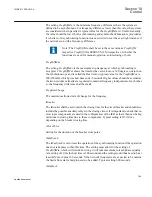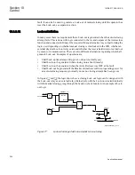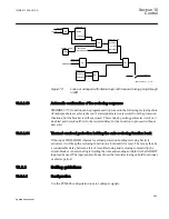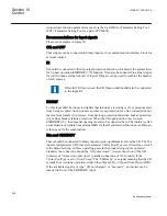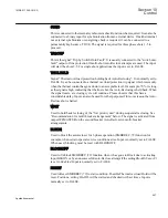
This setting is used to compensate the phase shift between the measured bus voltage and
line voltage when:
•
a. different phase-neutral voltages are selected (for example UL1 for bus and UL2 for
line);
•
b. one available voltage is phase-phase and the other one is phase-neutral (for
example UL1L2 for bus and UL1 for line).
The set value is added to the measured line phase angle. The bus voltage is reference
voltage.
If single phase UL1 or two-phase UL1L2 is not available, parameters
PhaseShift
and
URatio
can be used to compensate for other choices.
Table 14:
Voltage settings examples
Line voltage
Bus voltage
Bus voltage pre-
processing
SESRSYN setting
PhaseShift
URatio
UL1
UL1
Connect UL1 to
channel 1
-
1
UL2
Connect UL2 to
channel 1
- 120º
1
UL3
Connect UL3 to
channel 1
+ 120º
1
UL1L2
UL1L2
Connect UL1L2
to channel 1
-
1
UL2L3
Connect UL2L3
to channel 1
- 120º
1
UL3L1
Connect UL3L1
to channel 1
+ 120º
1
UL1
UL1L2
Connect UL1L2
to channel 1
- 30º
1.73
UL2L3
Connect UL2L3
to channel 1
- 90º
1.73
UL3L1
Connect UL3L1
to channel 1
+150º
1.73
Synchronizing settings
OperationSynch
The setting
Disabled
disables the Synchronizing function. With the setting
Enabled
, the
function is in service and the output signal depends on the input conditions.
FreqDiffMin
Section 10
1MRK 511 286-UUS A
Control
194
Application manual
Summary of Contents for REC650 ANSI
Page 1: ...Relion 650 series Bay control REC650 ANSI Application manual...
Page 2: ......
Page 26: ...20...
Page 66: ...Section 3 1MRK 511 286 UUS A REC650 setting examples 60 Application manual...
Page 71: ...IED IED ANSI05000460 V2 EN 1MRK 511 286 UUS A Section 4 Analog inputs 65 Application manual...
Page 82: ...76...
Page 92: ...86...
Page 170: ...164...
Page 176: ...170...
Page 274: ...268...
Page 288: ...282...
Page 350: ...344...
Page 369: ...363...

