


Table 7:
Alarm indications
LED state
Description
Off
Normal operation. All activation signals are off.
On
•
Follow-S sequence: The activation signal is on.
•
LatchedColl-S sequence: The activation signal is on, or it is off but the indication has
not been acknowledged.
•
LatchedAck-F-S sequence: The indication has been acknowledged, but the activation
signal is still on.
•
LatchedAck-S-F sequence: The activation signal is on, or it is off but the indication has
not been acknowledged.
•
LatchedReset-S sequence: The activation signal is on, or it is off but the indication has
not been acknowledged.
Flashing
•
Follow-F sequence: The activation signal is on.
•
LatchedAck-F-S sequence: The activation signal is on, or it is off but the indication has
not been acknowledged.
•
LatchedAck-S-F sequence: The indication has been acknowledged, but the activation
signal is still on.
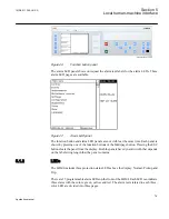
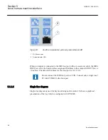
5.1.4.2
Parameter management
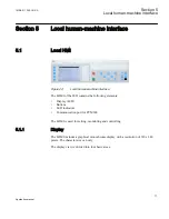
The LHMI is used to access the IED parameters. Three types of parameters can be read and
written.
•
Numerical values
•
String values
•
Enumerated values
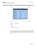
Numerical values are presented either in integer or in decimal format with minimum and
maximum values. Character strings can be edited character by character. Enumerated
values have a predefined set of selectable values.
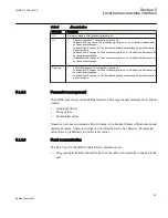
5.1.4.3
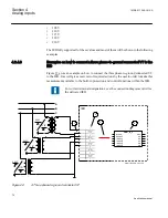
Front communication
The RJ-45 port in the LHMI enables front communication.
•
The green uplink LED on the left is lit when the cable is successfully connected to the
port.
1MRK 511 286-UUS A
Section 5
Local human-machine interface
83
Application manual
Summary of Contents for REC650 ANSI
Page 1: ...Relion 650 series Bay control REC650 ANSI Application manual...
Page 2: ......
Page 26: ...20...
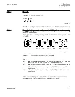
Page 66: ...Section 3 1MRK 511 286 UUS A REC650 setting examples 60 Application manual...
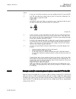
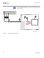
Page 71: ...IED IED ANSI05000460 V2 EN 1MRK 511 286 UUS A Section 4 Analog inputs 65 Application manual...
Page 82: ...76...
Page 92: ...86...
Page 170: ...164...
Page 176: ...170...
Page 274: ...268...
Page 288: ...282...
Page 350: ...344...
Page 369: ...363...


