


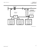


Protected Object
CT 800/1
Star Connected
IED
ANSI11000026-4-en.vsd
4
1
2
3
A
IA
IB
IC
B
C
IA
IB
IC
SMAI_20_2
BLOCK
REVROT
^GRP2L1
^GRP2L2
^GRP2L3
^GRP2N
AI3P
AI1
AI2
AI3
AI4
AIN
5
ANSI11000026 V4 EN
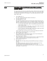
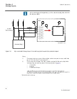
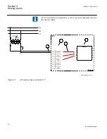
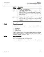
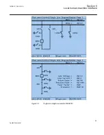
Figure 20:
Wye connected three-phase CT set with its star point away from the protected object
case everything is done in a similar way as in the above
described example (
). The only difference is the setting of the parameter
CTStarPoint
of the used current inputs on the TRM (item 2 in the figure):
•
CTprim
=600A
•
CTsec
=5A
•
CTWyePoint
=FromObject
Inside the IED only the ratio of the first two parameters is used. The third parameter as set
in this example will negate the measured currents in order to ensure that the currents are
measured towards the protected object within the IED.
4.2.4
Setting of voltage channels
As the IED uses primary system quantities the main VT ratios must be known to the IED.
This is done by setting the two parameters
VTsec
and
VTprim
for each voltage channel.
The phase-to-phase value can be used even if each channel is connected to a phase-to-
ground voltage from the VT.
Section 4
1MRK 511 286-UUS A
Analog inputs
70
Application manual
Summary of Contents for REC650 ANSI
Page 1: ...Relion 650 series Bay control REC650 ANSI Application manual...
Page 2: ......
Page 26: ...20...
Page 66: ...Section 3 1MRK 511 286 UUS A REC650 setting examples 60 Application manual...
Page 71: ...IED IED ANSI05000460 V2 EN 1MRK 511 286 UUS A Section 4 Analog inputs 65 Application manual...
Page 82: ...76...
Page 92: ...86...
Page 170: ...164...
Page 176: ...170...
Page 274: ...268...
Page 288: ...282...
Page 350: ...344...
Page 369: ...363...


