


WA1 (A1)
289
489G
189
389G
WA2 (A2)
en04000516_ansi.vsd
289G
189G
A1A2_BS
152
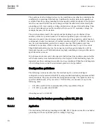
ANSI04000516 V1 EN
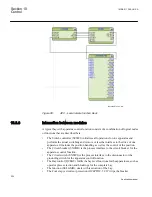
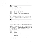
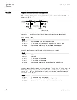
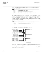
Figure 96:
Switchyard layout A1A2_BS (3)
The signals from other bays connected to the module A1A2_BS are described below.
10.4.5.2
Signals from all feeders
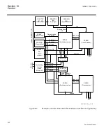
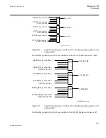
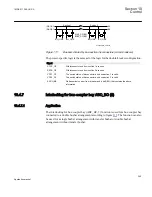
If the busbar is divided by bus-section circuit breakers into bus-sections and both circuit
breakers are closed, the opening of the circuit breaker must be blocked if a bus-coupler
connection exists between busbars on one bus-section side and if on the other bus-section
side a busbar transfer is in progress:
en04000489_ansi.vsd
Section 1
Section 2
A1A2_BS
B1B2_BS
ABC_LINE
ABC_BC
ABC_LINE
ABC_BC
(WA1)A1
(WA2)B1
(WA7)C
C
B2
A2
AB_TRAFO
AB_TRAFO
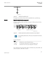
ANSI04000489 V1 EN
Figure 97:
Busbars divided by bus-section circuit breakers
The interlocking functionality in 650 series can not handle the transfer bus
(WA7)C.
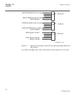
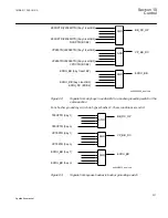
To derive the signals:
Section 10
1MRK 511 286-UUS A
Control
234
Application manual
Summary of Contents for REC650 ANSI
Page 1: ...Relion 650 series Bay control REC650 ANSI Application manual...
Page 2: ......
Page 26: ...20...
Page 66: ...Section 3 1MRK 511 286 UUS A REC650 setting examples 60 Application manual...
Page 71: ...IED IED ANSI05000460 V2 EN 1MRK 511 286 UUS A Section 4 Analog inputs 65 Application manual...
Page 82: ...76...
Page 92: ...86...
Page 170: ...164...
Page 176: ...170...
Page 274: ...268...
Page 288: ...282...
Page 350: ...344...
Page 369: ...363...


