


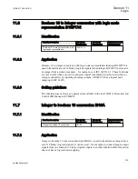


IEC09000310-1-en.vsd
IEC09000310 V1 EN
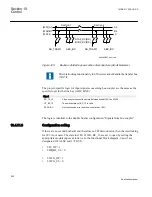
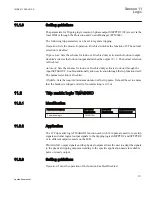
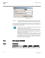
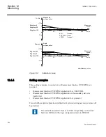
Figure 129:
Example designation, serial execution number and cycle time for logic
function that also propagates timestamp and quality of input signals
The execution of different function blocks within the same cycle is determined by the
order of their serial execution numbers. Always remember this when connecting two or
more logical function blocks in series.
Always be careful when connecting function blocks with a fast cycle time
to function blocks with a slow cycle time.
Remember to design the logic circuits carefully and always check the
execution sequence for different functions. In other cases, additional time
delays must be introduced into the logic schemes to prevent errors, for
example, race between functions.
Default value on all four inputs of the AND and ANDQT gate are logical
1 which makes it possible for the user to just use the required number of
inputs and leave the rest un-connected. The output OUT has a default
value 0 initially, which will suppress one cycle pulse if the function has
been put in the wrong execution order.
11.4
Fixed signals FXDSIGN
11.4.1
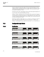
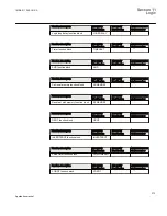
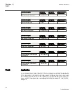
Identification
Function description
IEC 61850
identification
IEC 60617
identification
ANSI/IEEE C37.2
device number
Fixed signals
FXDSIGN
-
-
Section 11
1MRK 511 286-UUS A
Logic
276
Application manual
Summary of Contents for REC650 ANSI
Page 1: ...Relion 650 series Bay control REC650 ANSI Application manual...
Page 2: ......
Page 26: ...20...
Page 66: ...Section 3 1MRK 511 286 UUS A REC650 setting examples 60 Application manual...
Page 71: ...IED IED ANSI05000460 V2 EN 1MRK 511 286 UUS A Section 4 Analog inputs 65 Application manual...
Page 82: ...76...
Page 92: ...86...
Page 170: ...164...
Page 176: ...170...
Page 274: ...268...
Page 288: ...282...
Page 350: ...344...
Page 369: ...363...


