
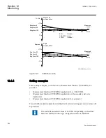


Postfault recording time (
PostFaultRecT
) is the maximum recording time after the
disappearance of the trig-signal (does not influence the Trip value recorder function).
Recording time limit (
TimeLimit
) is the maximum recording time after trig. The parameter
limits the recording time if some trigging condition (fault-time) is very long or
permanently set (does not influence the Trip value recorder function).
Post retrigger (
PostRetrig
) can be set to
Enabled
or
Disabled
. Makes it possible to choose
performance of Disturbance report function if a new trig signal appears in the post-fault
window.
PostRetrig
=
Disabled
The function is insensitive for new trig signals during post fault time.
PostRetrig
=
Enabled
The function completes current report and starts a new complete report that is, the latter
will include:
•
new pre-fault- and fault-time (which will overlap previous report)
•
events and indications might be saved in the previous report too, due to overlap
•
new trip value calculations if installed, in operation and started
Operation in test mode
If the IED is in test mode and
OpModeTest
=
Disabled
. Disturbance report function does
not save any recordings and no LED information is displayed.
If the IED is in test mode and
OpModeTest
=
Enabled
. Disturbance report function works
in normal mode and the status is indicated in the saved recording.
12.7.3.1
Binary input signals
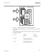
Up to 96 binary signals can be selected among internal logical and binary input signals.
The configuration tool is used to configure the signals.
For each of the 96 signals, it is also possible to select if the signal is to be used as a trigger
for the start of the Disturbance report and if the trigger should be activated on positive (1)
or negative (0) slope.
TrigDRN
: Disturbance report may trig for binary input N (
Enabled
) or not (
Disabled
).
TrigLevelN
: Trig on positive (
Trig on 1
) or negative (
Trig on 0
) slope for binary input N.
1MRK 511 286-UUS A
Section 12
Monitoring
299
Application manual
Summary of Contents for REC650 ANSI
Page 1: ...Relion 650 series Bay control REC650 ANSI Application manual...
Page 2: ......
Page 26: ...20...
Page 66: ...Section 3 1MRK 511 286 UUS A REC650 setting examples 60 Application manual...
Page 71: ...IED IED ANSI05000460 V2 EN 1MRK 511 286 UUS A Section 4 Analog inputs 65 Application manual...
Page 82: ...76...
Page 92: ...86...
Page 170: ...164...
Page 176: ...170...
Page 274: ...268...
Page 288: ...282...
Page 350: ...344...
Page 369: ...363...


