


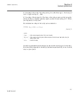

As the magnitude of the residual current is independent of the fault location the selectivity
of the ground-fault protection is achieved by time selectivity.
When should the sensitive directional residual overcurrent protection be used and when
should the sensitive directional residual power protection be used? Consider the following
facts:
•
Sensitive directional residual overcurrent protection gives possibility for better
sensitivity. The setting possibilities of this function are down to 0.25 % of IBase, 1 A
or 5 A. This sensitivity is in most cases sufficient in high impedance network
applications, if the measuring CT ratio is not too high.
•
Sensitive directional residual power protection gives possibility to use inverse time
characteristics. This is applicable in large high impedance grounded networks, with
large capacitive ground-fault current
•
In some power systems a medium size neutral point resistor is used, for example, in
low impedance grounded system. Such a resistor will give a resistive ground-fault
current component of about 200 - 400 A at a zero resistive phase-to-ground fault. In
such a system the directional residual power protection gives better possibilities for
selectivity enabled by inverse time power characteristics.
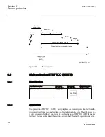
Phase
currents
Phase-
ground
voltages
IN
UN
IEC13000013-1-en.vsd
IEC13000013 V1 EN
Figure 52:
Connection of SDEPSDE to analog preprocessing function block
Over current functionality uses true 3I0, i.e. sum of GRPxL1, GRPxL2 and GRPxL3. For
3I0 to be calculated, connection is needed to all three phase inputs.
Directional and power functionality uses IN and UN. If a connection is made to GRPxN
this signal is used, else if connection is made to all inputs GRPxL1, GRPxL2 and GRPxL3
the sum of these inputs (3I0 and 3U0) will be used.
1MRK 511 286-UUS A
Section 6
Current protection
119
Application manual
Summary of Contents for REC650 ANSI
Page 1: ...Relion 650 series Bay control REC650 ANSI Application manual...
Page 2: ......
Page 26: ...20...
Page 66: ...Section 3 1MRK 511 286 UUS A REC650 setting examples 60 Application manual...
Page 71: ...IED IED ANSI05000460 V2 EN 1MRK 511 286 UUS A Section 4 Analog inputs 65 Application manual...
Page 82: ...76...
Page 92: ...86...
Page 170: ...164...
Page 176: ...170...
Page 274: ...268...
Page 288: ...282...
Page 350: ...344...
Page 369: ...363...


