


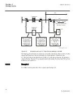
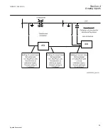


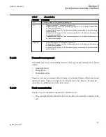

For correct terminal designations, see the connection diagrams valid for
the delivered IED.
Protected Object
CT 600/5
Star Connected
IED
ANSI3000002-2-en.vsd
1
2
3
4
SMAI_20
A
I_
A
I_
B
I_
C
B
C
I_A
I_B
I_C
ANSI13000002 V2 EN
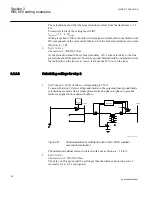
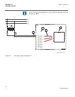
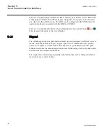
Figure 19:
Wye connected three-phase CT set with wye point towards the protected object
Where:
1)
The drawing shows how to connect three individual phase currents from a wye connected three-
phase CT set to the three CT inputs of the IED.
2)
The current inputs are located in the TRM. It shall be noted that for all these current inputs the
following setting values shall be entered for the example shown in
.
•
CTprim=600A
•
CTsec=5A
•
CTStarPoint=ToObject
Inside the IED only the ratio of the first two parameters is used. The third parameter
(CTStarPoint=ToObject) as set in this example causes no change on the measured currents. In
other words, currents are already measured towards the protected object.
Table continues on next page
Section 4
1MRK 511 286-UUS A
Analog inputs
68
Application manual
Summary of Contents for REC650 ANSI
Page 1: ...Relion 650 series Bay control REC650 ANSI Application manual...
Page 2: ......
Page 26: ...20...
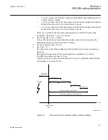
Page 66: ...Section 3 1MRK 511 286 UUS A REC650 setting examples 60 Application manual...
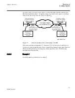
Page 71: ...IED IED ANSI05000460 V2 EN 1MRK 511 286 UUS A Section 4 Analog inputs 65 Application manual...
Page 82: ...76...
Page 92: ...86...
Page 170: ...164...
Page 176: ...170...
Page 274: ...268...
Page 288: ...282...
Page 350: ...344...
Page 369: ...363...


