


~
~
Z
A
Z
B
Z
L
A
B
IED
I
fB
Fault
ANSI09000022-1-en.vsd
ANSI09000022 V1 EN
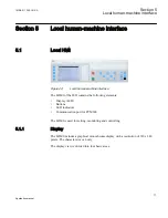
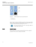
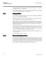
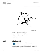
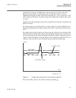
Figure 31:
Through fault current from A to B: I
fB
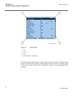
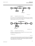
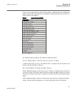
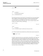
Then a fault in A has to be applied and the through fault current I
fA
has to be calculated,
figure
. In order to get the maximum through fault current, the minimum value for Z
B
and the maximum value for Z
A
have to be considered.
ANSI09000023-1-en.vsd
~
~
Z
A
Z
B
Z
L
A
B
IED
I
fA
Fault
ANSI09000023 V1 EN
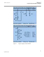
Figure 32:
Through fault current from B to A: I
fA
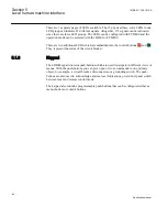
The IED must not trip for any of the two through-fault currents. Hence the minimum
theoretical current setting (Imin) will be:
Imin MAX I
fA
I
fB
,
(
)
³
EQUATION78 V1 EN
(Equation 23)
A safety margin of 5% for the maximum protection static inaccuracy and a safety margin
of 5% for the maximum possible transient overreach have to be introduced. An additional
20% is suggested due to the inaccuracy of the instrument transformers under transient
conditions and inaccuracy in the system data.
1MRK 511 286-UUS A
Section 6
Current protection
89
Application manual
Summary of Contents for REC650 ANSI
Page 1: ...Relion 650 series Bay control REC650 ANSI Application manual...
Page 2: ......
Page 26: ...20...
Page 66: ...Section 3 1MRK 511 286 UUS A REC650 setting examples 60 Application manual...
Page 71: ...IED IED ANSI05000460 V2 EN 1MRK 511 286 UUS A Section 4 Analog inputs 65 Application manual...
Page 82: ...76...
Page 92: ...86...
Page 170: ...164...
Page 176: ...170...
Page 274: ...268...
Page 288: ...282...
Page 350: ...344...
Page 369: ...363...


