


5.1.4
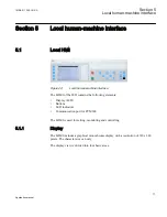
Local HMI functionality
5.1.4.1
Protection and alarm indication
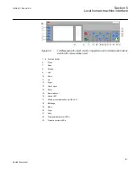
Protection indicators
The protection indicator LEDs are Normal, Pickup and Trip.
Table 4:
Normal LED (green)
LED state
Description
Off
Auxiliary supply voltage is disconnected.
On
Normal operation.
Flashing
Internal fault has occurred.
Table 5:
PickUp LED (yellow)
LED state
Description
Off
Normal operation.
On
A protection function has picked up and an indication message is displayed.
•
If several protection functions Pickup within a short time, the last Pickup is
indicated on the display.
Flashing
A flashing yellow LED has a higher priority than a steady yellow LED.
The IED is in test mode and protection functions are blocked.
•
The indication disappears when the IED is no longer in test mode and
blocking is removed.
Table 6:
Trip LED (red)
LED state
Description
Off
Normal operation.
On
A protection function has tripped and an indication message is displayed.
•
The trip indication is latching and must be reset via communication or by
pressing
.
Alarm indicators
The 15 programmable three-color LEDs are used for alarm indication. An individual
alarm/status signal, connected to any of the LED function blocks, can be assigned to one
of the three LED colors when configuring the IED.
Section 5
1MRK 511 286-UUS A
Local human-machine interface
82
Application manual
Summary of Contents for REC650 ANSI
Page 1: ...Relion 650 series Bay control REC650 ANSI Application manual...
Page 2: ......
Page 26: ...20...
Page 66: ...Section 3 1MRK 511 286 UUS A REC650 setting examples 60 Application manual...
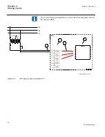
Page 71: ...IED IED ANSI05000460 V2 EN 1MRK 511 286 UUS A Section 4 Analog inputs 65 Application manual...
Page 82: ...76...
Page 92: ...86...
Page 170: ...164...
Page 176: ...170...
Page 274: ...268...
Page 288: ...282...
Page 350: ...344...
Page 369: ...363...


