


WA1 (A)
WA2 (B)
189
189G
289G
989G
6189
989
289
489G
589G
389G
6289
DB_BUS_B
DB_LINE
DB_BUS_A
en04000518_ansi.vsd
252
152
ANSI04000518 V1 EN
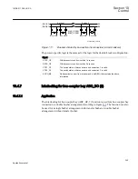
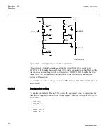
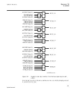
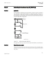
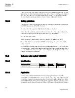
Figure 119:
Switchyard layout double circuit breaker
Three types of interlocking modules per double circuit breaker bay are defined.
DB_BUS_A (3) handles the circuit breaker QA1 that is connected to busbar WA1 and the
disconnectors and earthing switches of this section. DB_BUS_B (3) handles the circuit
breaker QA2 that is connected to busbar WA2 and the disconnectors and earthing
switches of this section.
For a double circuit-breaker bay, the modules DB_BUS_A, DB_LINE and DB_BUS_B
must be used.
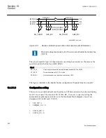
10.4.9.2
Configuration setting
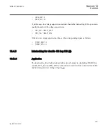
For application without 989 and 989G, just set the appropriate inputs to open state and
disregard the outputs. In the functional block diagram, 0 and 1 are designated 0=FALSE
and 1=TRUE:
•
989_OP = 1
•
989_CL = 0
•
989G_OP = 1
•
989G_CL = 0
Section 10
1MRK 511 286-UUS A
Control
254
Application manual
Summary of Contents for REC650 ANSI
Page 1: ...Relion 650 series Bay control REC650 ANSI Application manual...
Page 2: ......
Page 26: ...20...
Page 66: ...Section 3 1MRK 511 286 UUS A REC650 setting examples 60 Application manual...
Page 71: ...IED IED ANSI05000460 V2 EN 1MRK 511 286 UUS A Section 4 Analog inputs 65 Application manual...
Page 82: ...76...
Page 92: ...86...
Page 170: ...164...
Page 176: ...170...
Page 274: ...268...
Page 288: ...282...
Page 350: ...344...
Page 369: ...363...


