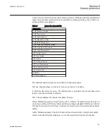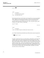
Curve name
IEC Definite Time
ASEA RI
RXIDG (logarithmic)
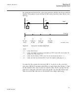
Power transformers can have a large inrush current, when being energized. This inrush
current can have residual current components. The phenomenon is due to saturation of the
transformer magnetic core during parts of the cycle. There is a risk that inrush current will
give a residual current that reaches level above the pickup current of the residual
overcurrent protection. The inrush current has a large second harmonic content. This can
be used to avoid unwanted operation of the protection. Therefore, EF4PTOC (51N_67N)
has a possibility of second harmonic restrain
2ndHarmStab
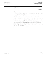
if the level of this harmonic
current reaches a value above a set percentage of the fundamental current.
6.4.3
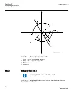
Setting guidelines
When inverse time overcurrent characteristic is selected, the operate time
of the stage will be the sum of the inverse time delay and the set definite
time delay. Thus, if only the inverse time delay is required, it is important
to set the definite time delay for that stage to zero.
The parameters for the four step residual overcurrent protection, zero or negative
sequence direction EF4PTOC (51N/67N) are set via the local HMI or PCM600.
The following settings can be done for the four step residual overcurrent protection.
GlobalBaseSel
: Selects the global base value group used by the function to define (
IBase
),
(
VBase
) and (
SBase
).
SeqTypeUPol
: It is used to select type of voltage polarization quantity, i.e.
ZeroSeq
and
NegSeq
for direction detection.
SeqTypeIPol
: It is used to select type of current polarization quantity, i.e.
ZeroSeq
and
NegSeq
for direction detection.
SeqTypeIDir
: It is used to select type of operating quantity, i.e.
ZeroSeq
and
NegSeq
for
direction detection.
Operation
: Sets the protection to
Enabled
or
Disabled
.
EnaDir
: Enables the directional calculation in addition to the directional mode selection
in each step.
Section 6
1MRK 511 286-UUS A
Current protection
108
Application manual
Summary of Contents for REC650 ANSI
Page 1: ...Relion 650 series Bay control REC650 ANSI Application manual...
Page 2: ......
Page 26: ...20...
Page 66: ...Section 3 1MRK 511 286 UUS A REC650 setting examples 60 Application manual...
Page 71: ...IED IED ANSI05000460 V2 EN 1MRK 511 286 UUS A Section 4 Analog inputs 65 Application manual...
Page 82: ...76...
Page 92: ...86...
Page 170: ...164...
Page 176: ...170...
Page 274: ...268...
Page 288: ...282...
Page 350: ...344...
Page 369: ...363...

