


2
,22
22
10
0.23
145
sc
Z
j
j
æ
ö
=
×
=
W
ç
÷
è
ø
GUID-FA8FA533-48E3-45FA-A22A-584CD0F754BF V1 EN
(Equation 3)
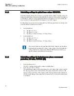
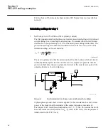
The transformer impedance referred to 22 kV level is:
2
,22
22
0.12
0.97
60
T
Z
j
j
=
×
=
W
GUID-78CEC42F-9A02-411B-B6D3-95017467242B V1 EN
(Equation 4)
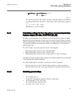
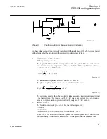
The fault current can be calculated as follows:
2
22000
3
3
948
2
0.23
0.97 3
10
sc ph
I
A
j
j
j
=
×
=
+
+ +
GUID-2C4DC073-E49B-45BB-8136-96B455CC57A1 V1 EN
(Equation 5)
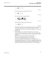
This fault current is recalculated to the 145 kV level:
2
,145
22
948 144
145
sc ph
I
A
=
×
=
GUID-2E36019B-9370-4703-9B31-91870BBD7BDB V1 EN
(Equation 6)
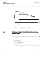
This current is smaller than the required minimum setting to avoid an unwanted trip
when experiencing a large load current. This means that the 145 kV phase
overcurrent protection cannot serve as complete back-up protection for the outgoing
22 kV feeders.
2.
Set
TD1
to
0.15
The time setting must be coordinated with the feeder protections to assure
selectivity. It can be stated that there is no need for selectivity between the high
voltage side phase overcurrent protection and the low voltage side phase overcurrent
protection.
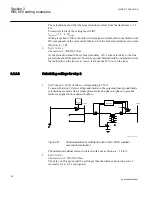
The feeder short circuit protections have the following setting:
Pickup1
: 300 A which corresponds to 45 A on 145 kV level.
Pickup1
: 6 000 A which corresponds to 910 A on 145 kV level.
Characterist
: IEC Normal Inverse (
IEC Norm. inv.
) with k-factor = 0.25
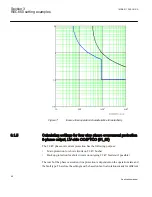
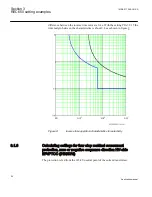
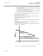
The setting of the k-factor for the 145 kV phase overcurrent protection is derived
from graphical study of the inverse time curves. It is required that the smallest time
difference between the inverse time curves shall be 0.4 s. With the setting
TD1
= 0.15
the time margin between the characteristics is about 0.4 s as shown in figure
1MRK 511 286-UUS A
Section 3
REC650 setting examples
45
Application manual
Summary of Contents for REC650 ANSI
Page 1: ...Relion 650 series Bay control REC650 ANSI Application manual...
Page 2: ......
Page 26: ...20...
Page 66: ...Section 3 1MRK 511 286 UUS A REC650 setting examples 60 Application manual...
Page 71: ...IED IED ANSI05000460 V2 EN 1MRK 511 286 UUS A Section 4 Analog inputs 65 Application manual...
Page 82: ...76...
Page 92: ...86...
Page 170: ...164...
Page 176: ...170...
Page 274: ...268...
Page 288: ...282...
Page 350: ...344...
Page 369: ...363...


