
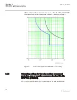


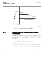


faults, fault points and switching states in the network. Although it is possible to make
manual calculations of the different faults it is recommended to use computer based fault
calculations.
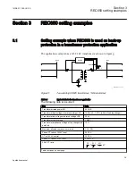
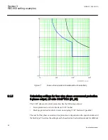
The following principle for the phase overcurrent protection is proposed:
•
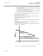
Step 1 serves as the main protection for the 22 kV busbar. This step has a short delay
and also has blocking input from the phase overcurrent protections of the 22 kV
feeders. This is a way to achieve a fast trip of 22 kV busbar short circuits while the
selectivity is realized by means of the blocking from the feeder protections.
•
Step 4 is used as back-up short circuit protection for the 22 kV feeders as far as
possible. The time delay principle is chosen according to network praxis, in this case
inverse time characteristics using IEC Normal inverse. As the step shall have an
inverse time characteristic the step 4 function is used.
An inverse time characteristics is not available for step 2 and 3.
3.1.5.1
Calculating general settings
1.
Set
GlobalBaseSel
to
2
The settings are made in primary values. These values are given in the base settings
in Global base 2.
2.
Set directional mode
2.1. Set
DirModeSel1
to
Non-directional
2.2. Set
DirModeSel4
to
Non-directional
The function shall be non-directional.
3.
Set
Characterist1
to
IEC Def.Time
Step 1 shall have definite time delay
4.
Set
Characterist4
to
IEC Norm.inv
Step 4: For the choice of the time delayed characteristic IEC Normal inverse is used
in this network.
3.1.5.2
Calculating settings for step 1
1.
Set
Pickup1
to
500 %
of
IBase
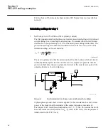
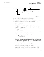
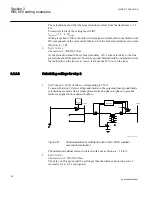
The requirement is that step 1 shall detect all short circuits on the 22 kV busbar. The
external network has a maximum source impedance of Z
sc
= j10 Ω (145 kV level).
This impedance is transformed to 22 kV level:
1MRK 511 286-UUS A
Section 3
REC650 setting examples
47
Application manual
Summary of Contents for REC650 ANSI
Page 1: ...Relion 650 series Bay control REC650 ANSI Application manual...
Page 2: ......
Page 26: ...20...
Page 66: ...Section 3 1MRK 511 286 UUS A REC650 setting examples 60 Application manual...
Page 71: ...IED IED ANSI05000460 V2 EN 1MRK 511 286 UUS A Section 4 Analog inputs 65 Application manual...
Page 82: ...76...
Page 92: ...86...
Page 170: ...164...
Page 176: ...170...
Page 274: ...268...
Page 288: ...282...
Page 350: ...344...
Page 369: ...363...


